SLOA250C July 2017 – June 2022 TAS2505 , TAS2505-Q1
4.4 Diagnostic Circuit #3
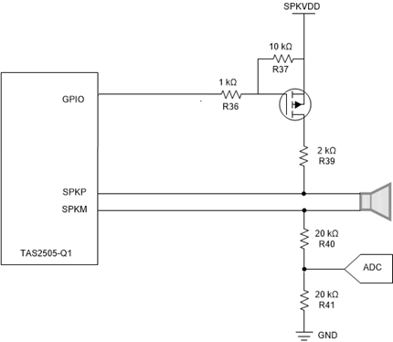
Figure 4-3 shows the third diagnostic circuit, which is similar to diagnostic circuit #2 with the exception that the third diagnostic circuit removes the BJT transistor used to control the MOSFET. The control logic is the inverse of circuit #2, so GPIO must be HIGH to disable the diagnostic circuit and set the device into Normal Operation; setting GPIO to LOW enables the circuit and open load test can be performed.
There is a tradeoff on removing the BJT, which is an increase in current consumption. For example, when TAS2505-Q1 is off, there is still current drawn if SPKVDD is on.
 Figure 4-3 Diagnostic Circuit #3
Schematic