SLOA250C July 2017 – June 2022 TAS2505 , TAS2505-Q1
4.1 Diagnostic Circuit #1
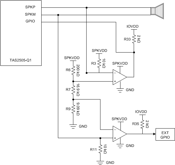
Diagnostics to detect an open load can be done externally with minimal impact to size and cost of the design. Figure 4-1 shows the first external load diagnostic circuit.
 Figure 4-1 Diagnostic Circuit #1 Schematic
The speaker must be connected to the SPKP and SPKM output points on J5 and J4 for this circuit to function properly. The circuit detects load faults by monitoring the non-inverting speaker line (SPKP) and the inverting speaker line (SPKM) of each channel. Abnormal voltages on each output line are identified by comparing reference voltages created by the resistor network of R6, R7, and R8 to the voltages on the output lines with a LM2903-Q1 dual comparator. If the voltage on one of the output lines is too high or too low, then the output of the comparator pulls the GPIO to ground. The output of the comparator is normally pulled high to IOVDD, and is pulled low when a fault occurs. The GPIO pin on the TAS2505-Q1 can be programmed as an input and then used to detect this change.
The output of the first comparator is connected to the TAS2505-Q1 as a GPIO input. Since the TAS2505-Q1 only has one GPIO input, the output of the second comparator can be connected to an external GPIO input of the MCU or ignored. Only one comparator is necessary for open load detection, but using two allows differentiation between the potential faults: short to power, short to ground, short between the speaker terminals, and open load. Table 4-1 and Table 4-2 show the fault conditions and the corresponding state of the comparators and registers.
To limit power draw during operation and minimize effects on audio performance, R3, R6, R7, R9, and R11 are high-impedance resistors. The value of R7 determines the reference voltages that the speaker terminals (SPKP and SPKM) are compared to for fault detection. This reference window is crucial for open load detection and therefore resistors with 1% or less tolerance should be used. The comparator goes low if the negative input is greater than the positive input.