SLUAAI3 January 2022 TPS62810-Q1 , TPS62811-Q1 , TPS62812-Q1 , TPS62813-Q1 , TPS62816-Q1 , TPS628501 , TPS628501-Q1 , TPS628502 , TPS628502-Q1 , TPS628503 , TPS628503-Q1 , TPS628510 , TPS628511 , TPS628512 , TPS62870 , TPS62870-Q1 , TPS62871 , TPS62871-Q1 , TPS62872 , TPS62872-Q1 , TPS62873 , TPS62873-Q1 , TPS62874-Q1 , TPS62875-Q1 , TPS62876-Q1 , TPS62877-Q1 , TPS62A01 , TPS62A01A , TPS62A02 , TPS62A02A , TPS62A06 , TPS62A06A , TPSM82810 , TPSM82813 , TPSM8287A06 , TPSM8287A10 , TPSM8287A12 , TPSM8287A15 , TPSM8287B30
3 System Setup and Calibration Elements
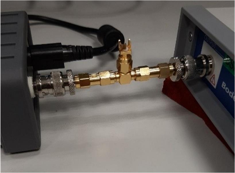
Before performing the measurement, a Thru calibration of the VNA is required to avoid additional series resistor and impedance mismatches. At high frequency, mismatches commonly appear. The use of a SMA connector is favored to eliminate mismatch errors. An SMA connector also offers a small size, light weight and a high frequency capable connector, up to 18 GHz.
 |
 |
The VNA and the semi-floating amplifier are connected by a SMA T-shaped connector as shown in Figure 3-1 and the third hole is connected to a calibration element.
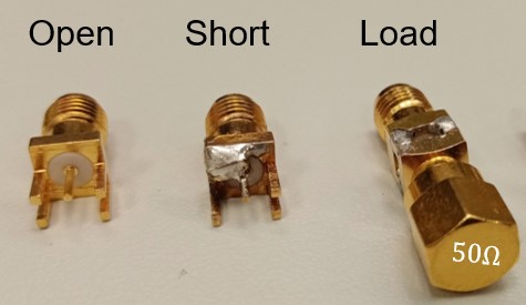
The calibration elements, as displayed in Figure 3-1 are very convenient for mounting typical bypass capacitor sizes. The distance between the center pin and the GND pin must have a similar size than the DUT. In the case of a PDN evaluation, the pads of a buck converter output capacitor. The calibration elements generally used are open circuits, short circuits and 50 Ohm loads. It is possible to use other reference elements like a capacitor, an inductor or a 1mOhm resistor to verify the quality of the calibration of the VNA. These elements can be purchased or handmade starting from a female SMA connector [6].
To ensure reliability and reproducibility of the impedance measurement, it is very important to verify measurement parameters of the VNA. The operating frequency range might be by default narrower than the full frequency range thus can be extended to evaluate a wider frequency range. The frequency window can also be reduced to minimize computing time. To avoid saturation in measurements, it is recommended to adjust the attenuation level on the receiver channel.
The applied signal can be modulated based on DUT. In general, higher signal levels offer less signal-to-noise ratio (SNR) in measured values. Though, impedance value of passive components like ceramic capacitors tends to vary with measurement signal level. The user would then need to adapt signal level over frequency.
If the calibration is not well performed, the system is subject to higher SNR and inaccuracies. This would prevent to measure a very low impedances over the full frequency range.
After the Thru Calibration, the DUT is ready to be connected to the system to start the measurements.
By cutting off some of the SMA connector GND pins, an SMA connector can be modified, as shown in Figure 3-2. An alternative method can be to use a SMA semi-rigid cable and cutting it short, stripping the center conductor and soldering a short pin to the outer conductor.