SLUUBM0D May 2017 – October 2020 TPS92518 , TPS92518-Q1 , TPS92518HV , TPS92518HV-Q1
- Trademarks
- 1Description
- 2Performance Specifications
- 3Performance Data and Typical Characteristic Curves
- 4Schematic, PCB Layout, and Bill of Materials
- 5Software
- 6Use of LEDSPIMCUEVM-879 Microcontroller Board for SPI Communications with the TPS92518
- 7Revision History
3.4.3 Shunt FET Dimming
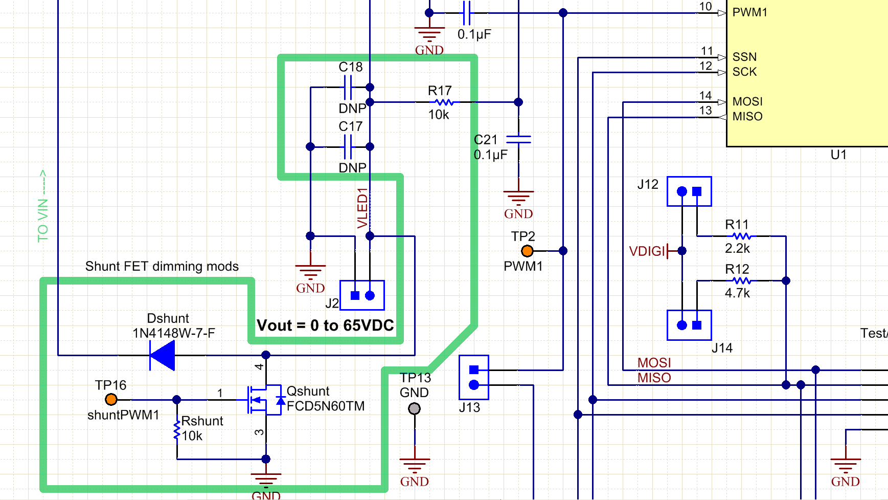
Shunt FET dimming is simple with the TPS92518. Short leads between the evaluation board and the LED load boards are important to prevent VLED overshoot. Locating the shunt FET on or near the LED load board also helps to reduce VLED overshoot. Adding an appropriately rated diode from the LED+ line that conducts back to the positive VIN input will clamp voltage overshoot.
There is no provision for mounting such a diode on the board: it must be soldered into the wiring used to connect the shunt FET into the circuit.
Similarly, repopulating R17 and C21 with different values will also protect the VLED pin from overshoots. The Figure 3-12, green high-lighted area, illustrates the circuitry modifications for shunt FET dimming if high overshoots are being seen. Adding/increasing the resistance at R17 and greatly reducing C21, OR adding a diode (shown as Dshunt) back to VIN are proven solutions. If adding R17 ensure a small C21 is used, like 220 pF, to allow the feedback enough bandwidth for correct output voltage sensing.
 Figure 3-12 Additional Circuitry Required
for Shunt FET Dimming