SLUUBN2A March 2017 – August 2021
- Trademarks
- 1 Introduction
- 2 Description
- 3 EVM Electrical Performance Specifications
- 4 Schematic
- 5 Test Setup
- 6 Test Equipment
- 7 PWR-847EVM
- 8 List of Test Points, Jumpers, and Switch
- 9 EVM Configuration Using the Fusion GUI
- 10Test Procedure
- 11Performance Data and Typical Characteristic Curves
- 12Fusion GUI
- 13EVM Assembly Drawing and PCB Layout
- 14List of Materials
- 15Revision History
12 Fusion GUI
Figure 12-1 through Figure 12-4 illustrate the Fusion GUI launch and installation dialog windows.
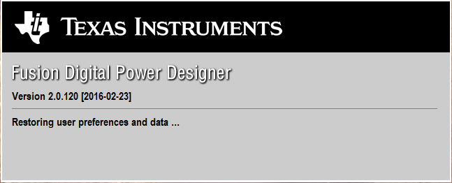 Figure 12-1 First Window at Fusion Launch
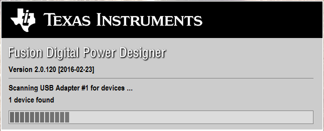 Figure 12-2 Scan Finds Device Successfully
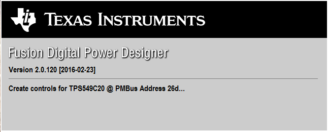 Figure 12-3 Software Launch Continued
 Figure 12-4 Software Launch Continued
Use the All Config tab to configure all of the configurable parameters (Figure 12-5). The screen also shows other details like hexadecimal (hex) encoding. Use this screen to configure:
- Power Good Delay
- Power On Delay
- Mode Settings
- Frequency, RAMP, DCAP3
- VDD UVLO
- On/Off Configuration
- Track and Sequencing
- Write Protect
- VOUT Command Voltage
- VOUT Margin
- Operation
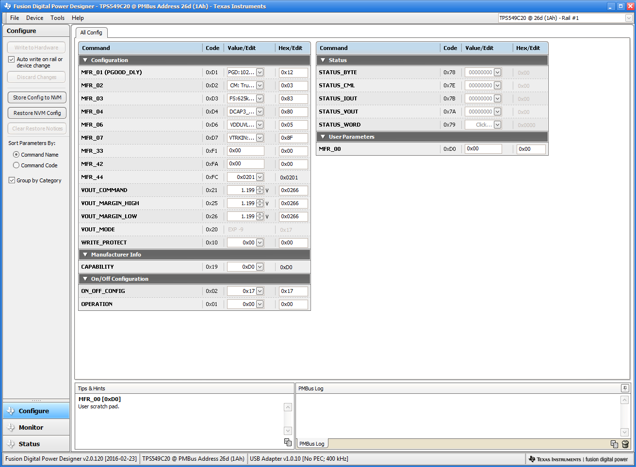 Figure 12-5 First Screen After Successful Launch Configure: Limits and On/Off
Changing the frequency prompts a pop-up window with details of the options Figure 12-6).
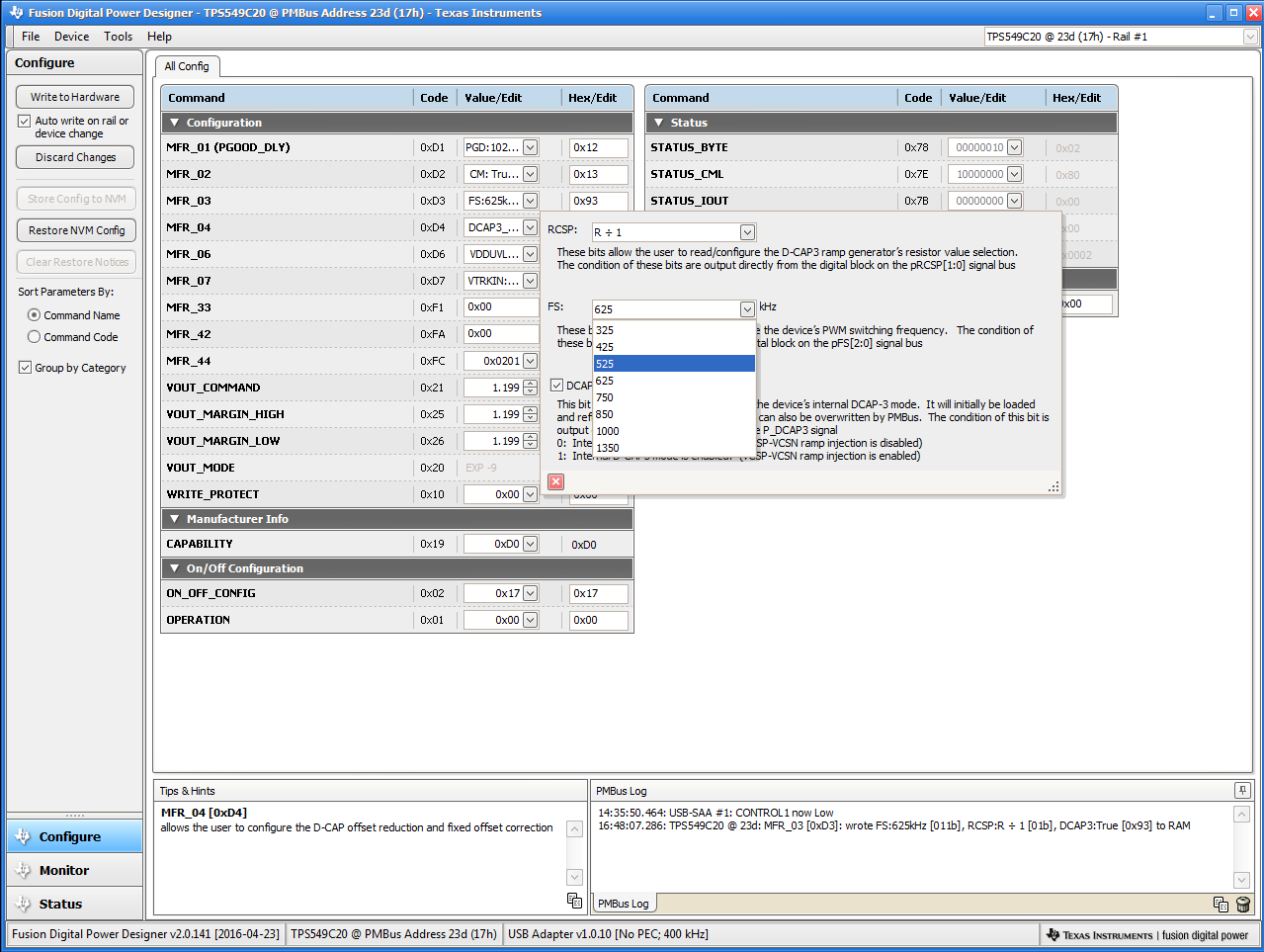 Figure 12-6 Configure: Frequency- FS Configuration Pop-up
After a change is selected, orange U icon is displayed to offer Undo Change option. Change is not retained until either Write to Hardware or Store Config to NVM is selected. When Write to Hardware is selected, change is committed to volatile memory and defaults back to previous setting on input power cycle. When Store Config to NVM is selected, change is committed to nonvolatile memory and becomes the new default (Figure 12-7).
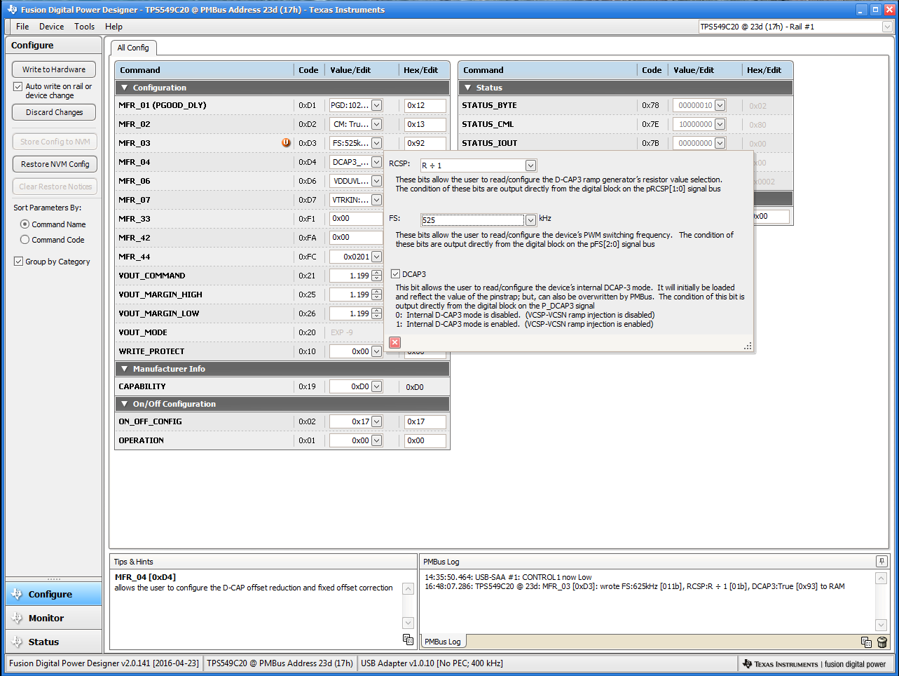 Figure 12-7 Configure: Frequency- FS Config Pop-Up with Change
After making changes to one or more configurable parameters, the changes can be committed to nonvolatile memory by selecting Store Config to NVM. This action prompts a confirm selection pop-up, and if confirmed, the changes are committed to nonvolatile memory (Figure 12-8).
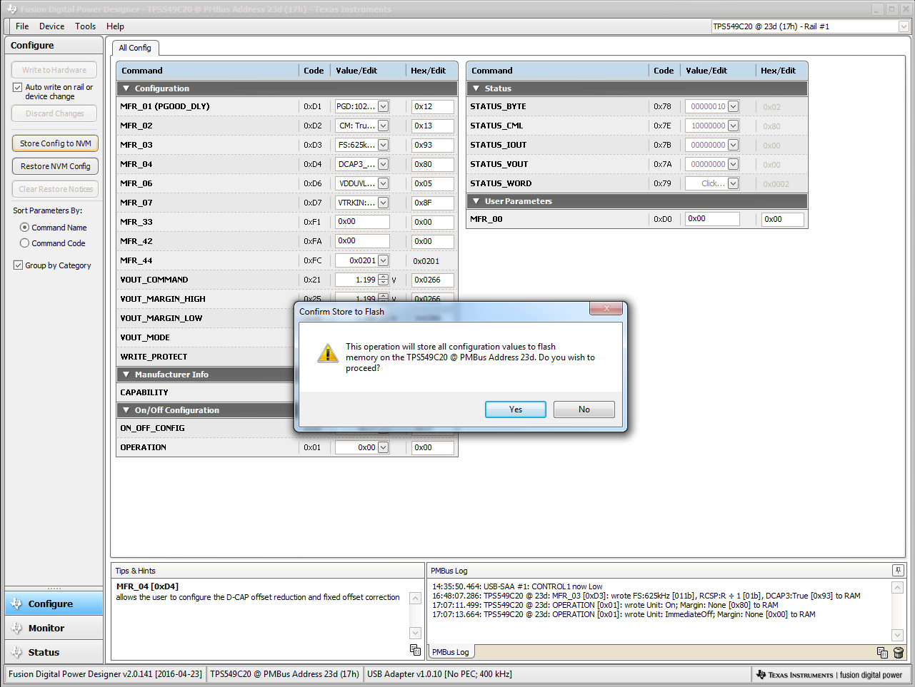 Figure 12-8 Configure: Store Config to NVM
In the lower left corner, the different view screens can be changed. The view screens can be changed between Configure, Monitor and Status as needed (Figure 12-9).
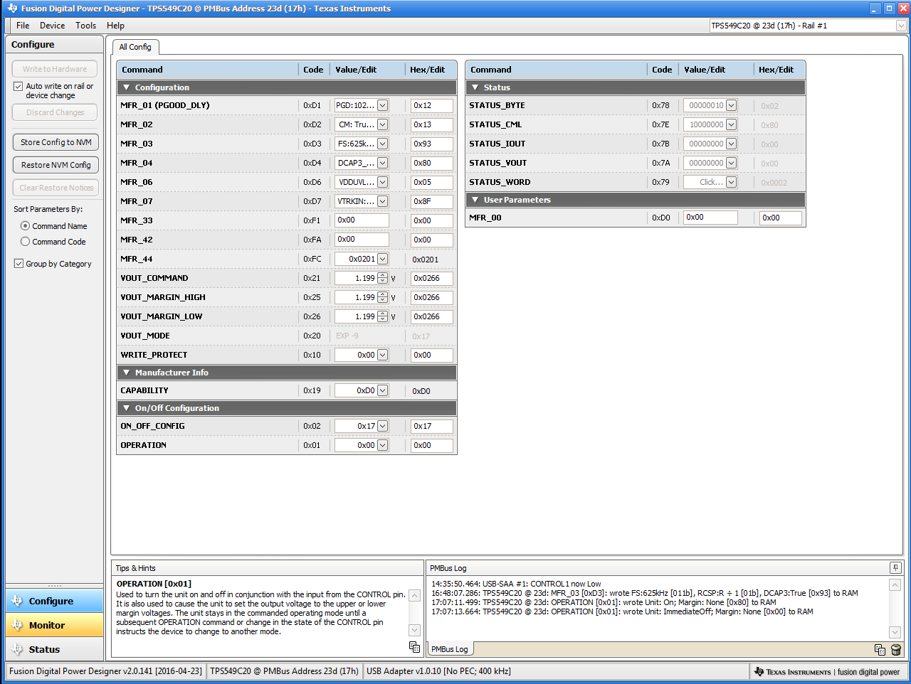 Figure 12-9 Change View Screen to Monitor Screen
Selecting System Dashboard from mid-left screen adds a new window which displays system-level information (Figure 12-10).
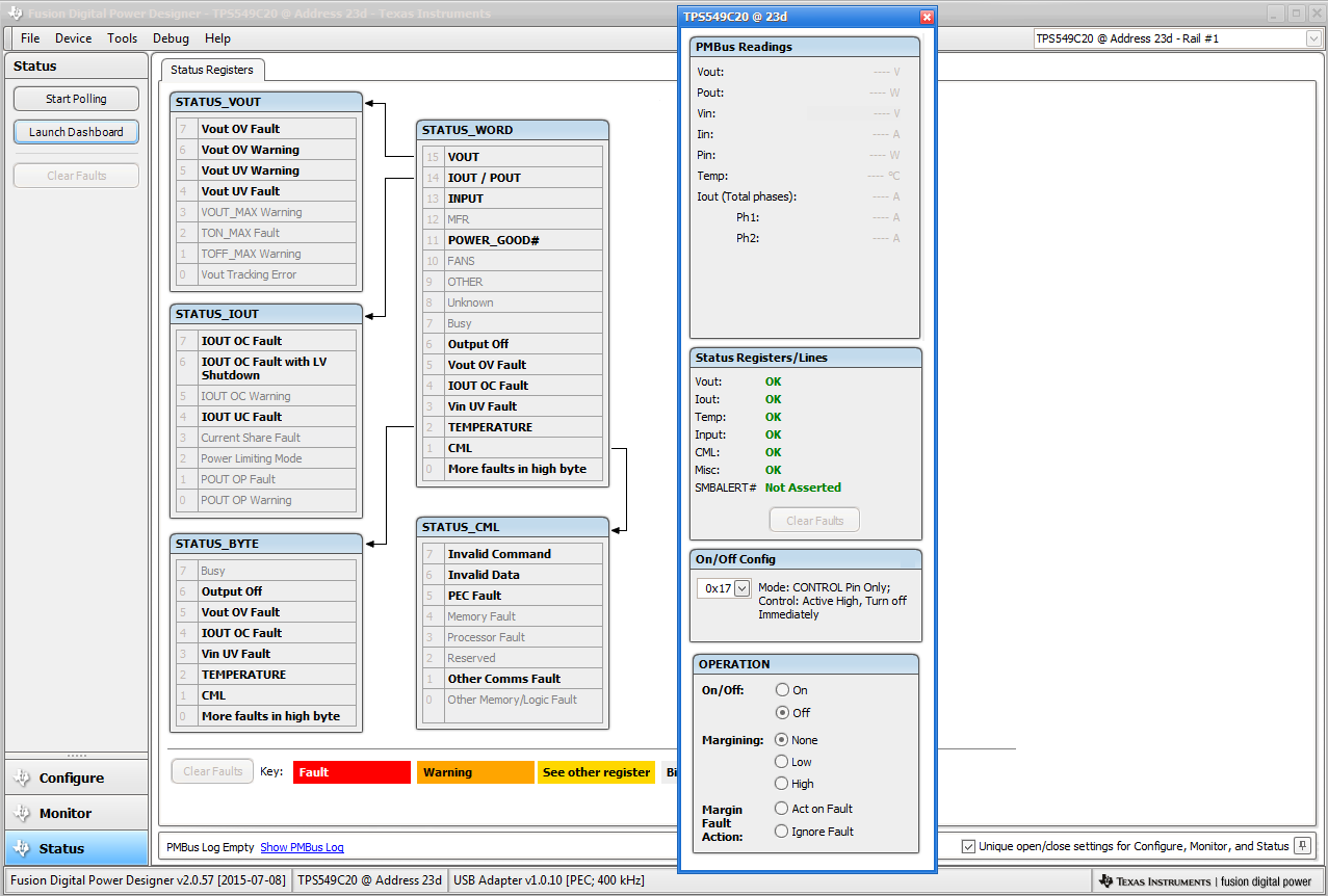 Figure 12-10 System Dashboard
Selecting Status from lower left corner shows the status of the controller (Figure 12-11).
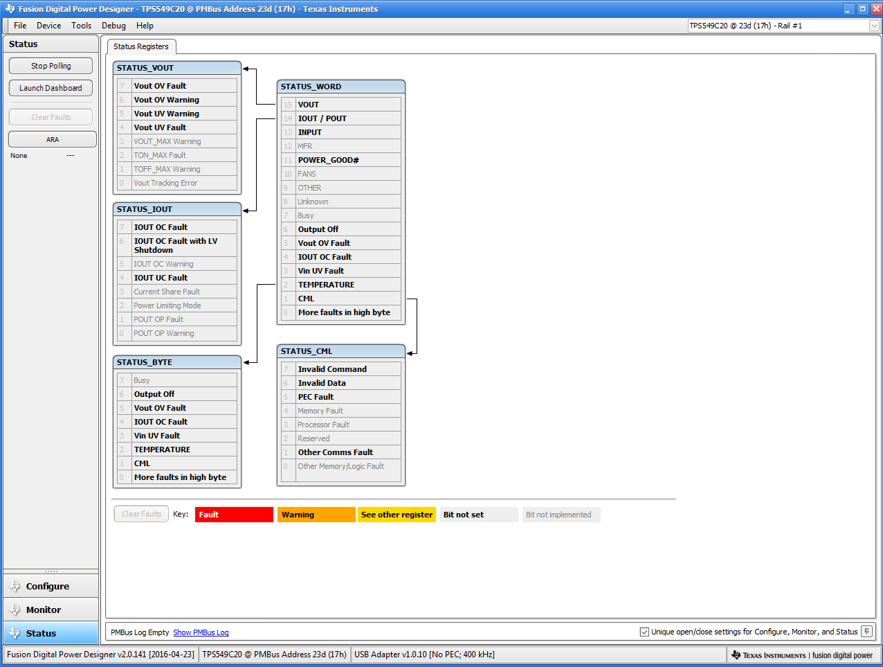 Figure 12-11 Status Screen
Selecting Store User Configuration to Flash Memory from the device pull-down menu has the same functionality as the Store Config to NVM button from the configure screen. It results in committing the current configuration to nonvolatile memory (Figure 12-12).
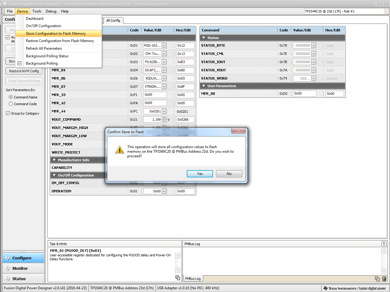 Figure 12-12 Store Configuration To Memory
Selecting PMBus Logging (Figure 12-13) from the Tools drop-down menu enables the logging of all PMBus activity. This includes communications traffic for each polling loop between the GUI and the device. The user is prompted to select a location for the file to be stored. See next screen (Figure 12-14).
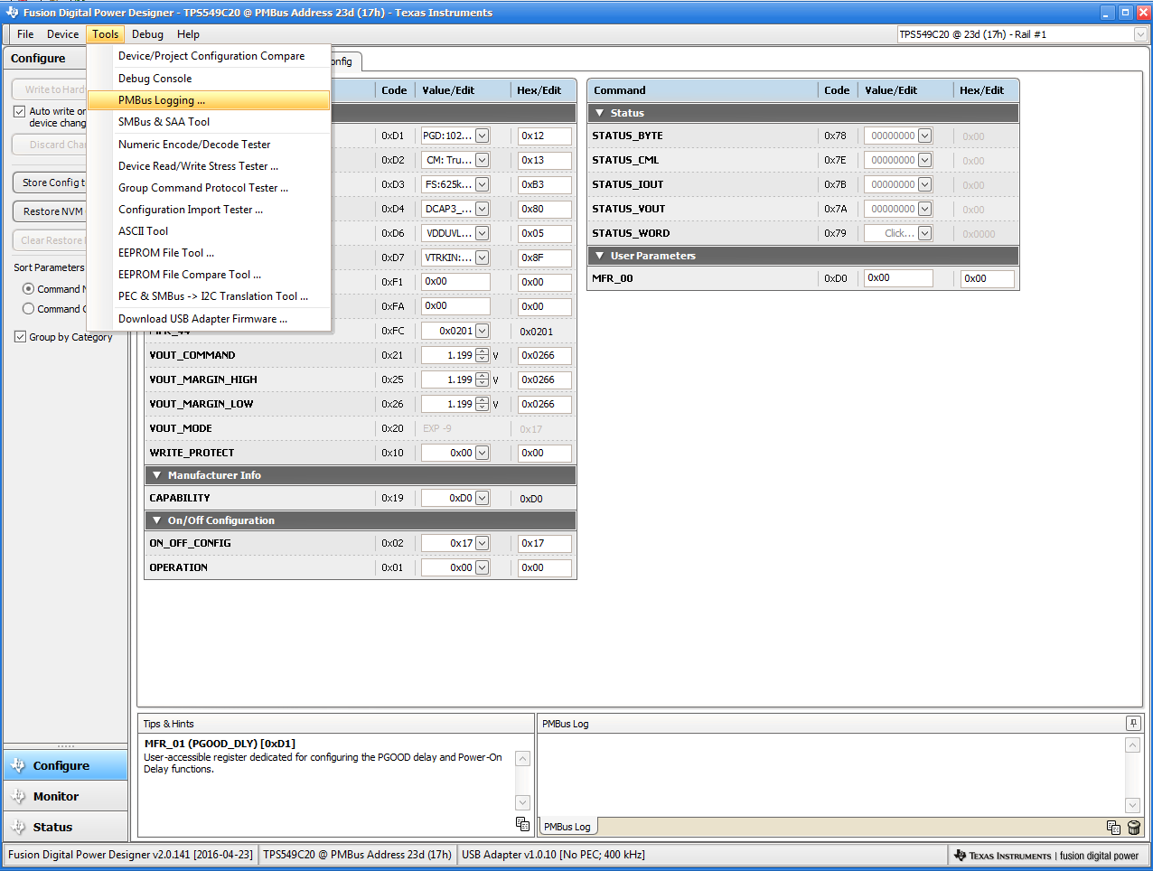 Figure 12-13 PMBus Logging
Select the storage location for the file and the type of file. As shown (Figure 12-14), the file is a CSV file to be stored in the directory path shown. Logging begins when the Start Logging button is selected, and stops when it is reselected (as Stop Logging). This file can rapidly grow in size, so caution is advised when using this function.
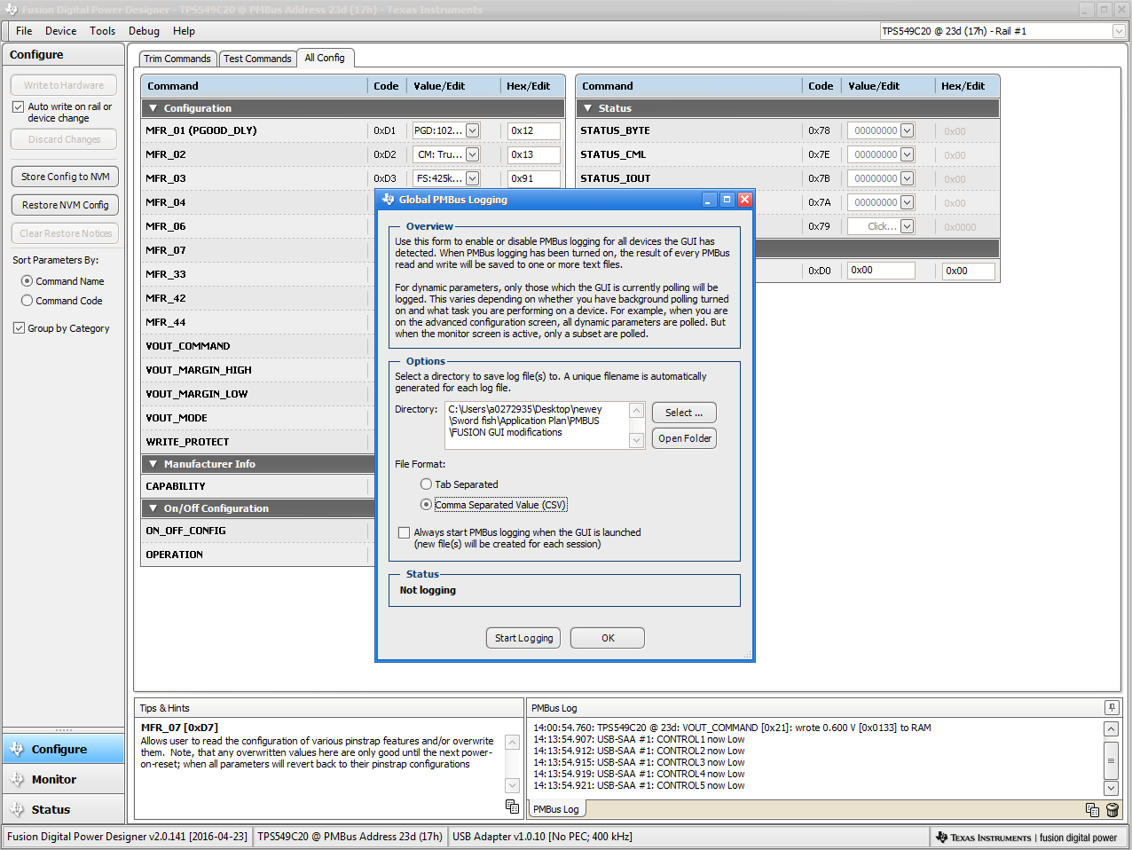 Figure 12-14 PMBus Log Details