SLUUCC7A September 2020 – April 2021
6.1 Schematic
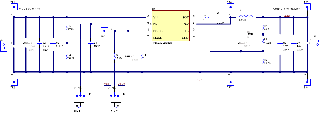
Figure 6-1 is the schematic for the TPS562211EVM.
 Figure 6-1 TPS562211EVM Schematic Diagram
SLUUCC7A September 2020 – April 2021
Figure 6-1 is the schematic for the TPS562211EVM.
 Figure 6-1 TPS562211EVM Schematic Diagram