SLUUCR0A September   2023  – December 2023


  1.   1
  2.   Description
  3.   Get Started
  4.   Features
  5.   Applications
  6.   6
  7. 1Evaluation Module Overview
    1. 1.1 Introduction
    2. 1.2 Kit Contents
    3. 1.3 Specifications
    4. 1.4 Device Information
  8. 2Hardware
    1. 2.1 I/O Information
    2. 2.2 Jumper Information
    3. 2.3 Equipment
    4. 2.4 Hardware Setup
  9. 3Software
    1. 3.1 Software Setup
    2. 3.2 Test Procedure
      1. 3.2.1 Initial Power Up
      2. 3.2.2 I2C Register Communication Verification
      3. 3.2.3 Charger Mode Verification
      4. 3.2.4 Boost Mode Verification
      5. 3.2.5 Helpful Tips
  10. 4Hardware Design Files
    1. 4.1 Schematic
    2. 4.2 PCB Layout
      1. 4.2.1 PCB Layout Guidelines
    3. 4.3 Bill of Materials (BOM)
  11. 5Additional Information
    1.     Trademarks
  12. 6Revision History

Boost Mode Verification

Use the following steps for boost mode verification:

  1. Turn off and disconnect PS #1.
  2. Set Load #1, the battery simulator, to 3.7V and 2 A current limit.
    Note: If Load #1 connected from BATTERY-J4(3) to GND-J4(1) is not a four quadrant supply, then remove Load #1 and use PS #1, set to 3.7V, 2 A current limit and connect to BATTERY-J4(3) and GND-J4(1).
  3. In the EVM software on the 16-bit tab, confirm that VOTG, the OTG regulation voltage, is set to 5040 mV and IOTG, the OTG current limit, is set to 1000 mA.
    GUID-F28FAFC1-476B-4919-8CC4-EE2AF0C8EF9E-low.svg
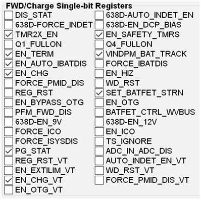
  4. In the EVM software on the 8-bit tab, check
    GUID-20230926-SS0I-JBNF-KQ8P-HR2SVLXL0BFB-low.gif
  5. Connect Load #2 across VPMID-J3(1) and PGND-J3(2).
  6. Set Load #2 to 500 mA constant current load and the turn on the load.
  7. To confirm the VOTG regulation,
    • Measure→ VBUS = 5040 mV + 155 mV
  8. Turn off and disconnect the power supply.
  9. Remove Load #2 from the connection.