SLVA321A August 2011 – April 2021 DRV8811 , DRV8818 , DRV8821 , DRV8823 , DRV8823-Q1
2.2 Slow Decay
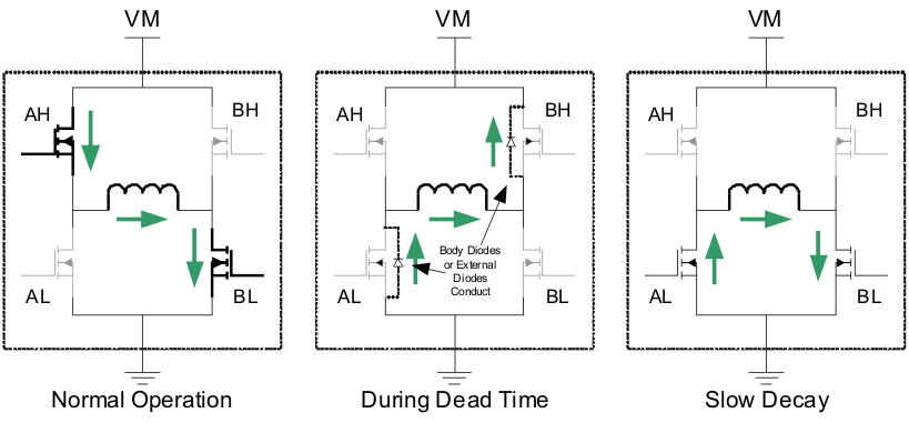
During a slow decay recirculation mode, current is said to decay towards zero on a slower than fast decay basis. Slow decay mode is attained by disabling the high side energizing FET switch and enabling the opposing low side FET switch.
 Figure 2-3 Slow Decay Mode
Although slow decay is often portrayed as both low side FET switches turned ON with both high side FET switches turned OFF, the same phenomenon can be achieved by enabling both high side FET switches, while disabling both low side FET switches. Some DRV88xx devices will allow for either technique to be employed by properly configuring the device through respective MODE input signals.
There are certain special characteristics to the slow decay mode that the user must understand:
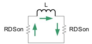
- Current will decay as slow as the LR time constant, where L is the inductance on the inductive load and R is two times the low side switch RDSon.
 Figure 2-4 Current Decay
 - On DC motors, where a Back EMF develops as the motor rotates, slow decay mode offers a short to the winding, which in turn shorts (collapses) the Back EMF. This results in a very quick rotor stop.