SLVAEE9A October 2019 – July 2021 TPS2065C , TPS2065D , TPS2069C , TPS2069D , TPS25221
3.1 With RC Filter to Eliminate Fault Glitch as Start-Up
 Figure 3-1 Solution for Fault Glitch
Adding the RC filter between the Fault and MCU to eliminate the glitch.
Since point B from Figure 2-1 is in unknown status until VIN reaches UVLO (4 V, the worst case in TPS2065D or TPS2069D). The worst case for Fault low is from Vin = Vth to Vin reach UVLO.
If Vin = 5 V, and VIN ramp = Vramp V/ms, the worst Fault low period TFAULT_L = (UVLO - Vth) / Vramp. You need Fault_A to be > VFAULT_H (1.7 V) during TFAULT_L. VFAULTd_H according to the customer's definition. Before power on, the initial voltage on C1 is 3.3 V. Before Vin reaches the UVLO voltage threshold, the voltage on C1 discharges through the FLT pin to GND.
Select RC value to make sure:
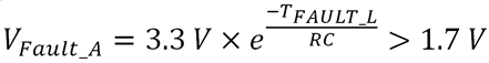
If Vramp = 5 V/ms, then TFAULT_L = 0.6 ms, select R = 1kΩ, C=1 µF.
 Figure 3-2 Without RC Filter Waveform, 5 V/ms
 Figure 3-3 With RC Filter Waveform, 5 V/ms
As seen in Figure 3-2, without the RC filter added, the Fault pin is pulled down to 0 V. The duration time depends on the slew rate of input. Figure 3-3 displays that with the RC filter added, although the Fault pin has a glitch, the terminal Fault_A that is connected to MCU almost has no glitches, always high level. The method proposed can eliminate the fault glitch concern.