SLVAEQ2 April 2020 TPS2549-Q1 , TPS254900-Q1 , TPS254900A-Q1 , TPS2556-Q1 , TPS2557-Q1 , TPS2559-Q1 , TPS25830-Q1 , TPS25831-Q1 , TPS25832-Q1 , TPS25833-Q1 , TPS25840-Q1 , TPS25842-Q1
-
How to Pass MFi Overcurrent Protection Test With USB Charger and Switch Device
- Trademarks
- 1 The Instruction of MFi OCP Requirement
- 2 Test Standard and Requirements
- 3
The Solution to Pass MFi OCP Test
- 3.1 Solution 1: Increasing Current Limit Point Higher Than 1.6*Ia
- 3.2
Solution 2: Paralleling RC With Rlimit to Delay the Current Limit Response
- 3.2.1 For the 1.5A USB Port With External FET
- 3.2.2 For the 1.5A Port Without External FET
- 3.2.3 For 2.1A USB Port With External FET
- 3.2.4 For 2.1A USB Port Without External FET
- 3.2.5 For 2.4A USB Port With External FET
- 3.2.6 For 2.4A USB Port Without External FET
- 3.2.7 For 3A USB Port With External FET
- 3.2.8 For 3A USB Port Without FET
- 4 Summary
- 5 References
2 Test Standard and Requirements
The following test setup and requirements are based on the TPS2583X/4X-Q1 EVM to pass MFi OCP test:
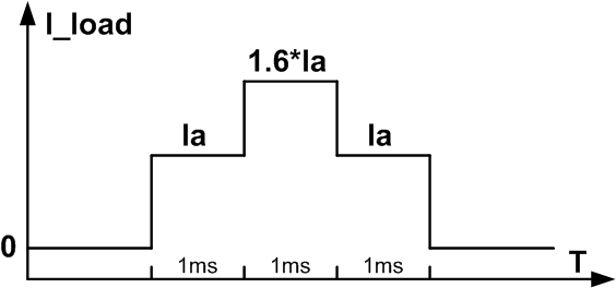
- The test load waveform is shown in Figure 2.
- The test setup between the TPS2583x/4x-Q1 EVM and E-load includes lightning cable, test connection board. The setup as Figure 3.
- In practice, whether the test is passed is determined by whether the voltage at the E-load drops to 0 V.
- Due to the voltage drop on the cable and some characteristic of the connection board, the output voltage of TPS2583x/4x-Q1 should be higher to pass the test.
 Figure 2. Load Waveform of MFi OCP Test
  Figure 3. TPS2583x/4x-Q1 EVM MFi OCP Test Setup