SLVAEQ2 April 2020 TPS2549-Q1 , TPS254900-Q1 , TPS254900A-Q1 , TPS2556-Q1 , TPS2557-Q1 , TPS2559-Q1 , TPS25830-Q1 , TPS25831-Q1 , TPS25832-Q1 , TPS25833-Q1 , TPS25840-Q1 , TPS25842-Q1
-
How to Pass MFi Overcurrent Protection Test With USB Charger and Switch Device
- Trademarks
- 1 The Instruction of MFi OCP Requirement
- 2 Test Standard and Requirements
- 3
The Solution to Pass MFi OCP Test
- 3.1 Solution 1: Increasing Current Limit Point Higher Than 1.6*Ia
- 3.2
Solution 2: Paralleling RC With Rlimit to Delay the Current Limit Response
- 3.2.1 For the 1.5A USB Port With External FET
- 3.2.2 For the 1.5A Port Without External FET
- 3.2.3 For 2.1A USB Port With External FET
- 3.2.4 For 2.1A USB Port Without External FET
- 3.2.5 For 2.4A USB Port With External FET
- 3.2.6 For 2.4A USB Port Without External FET
- 3.2.7 For 3A USB Port With External FET
- 3.2.8 For 3A USB Port Without FET
- 4 Summary
- 5 References
3 The Solution to Pass MFi OCP Test
Due to the load waveform of the OCP test related to Ia, the different applications need to be sorted by current. For standard USB type-A and type-C applications, the typical current type is 1.5A, 2.1A, 2.4A and 3A. Previously, you needed to respond quickly to overcurrent by either turning off the output voltage or limiting the current. Now, to pass the MFi OCP test, the device should not shutdown the current and the voltage cannot have a big drop. In view of this situation, here are two solutions:
- Increase the current limit point higher than 1.6*Ia, when the IC support 1.6*Ia continues current.
- Set the normal current limit, such as 1.2*Ia, paralleling RC with Rlimit to delay the current limit response. This solution can apply to just TPS2583x/4x-Q1.
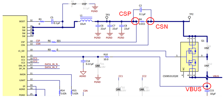
These two solutions are the main ideas. Sometimes, capacitors need to be added to make up the IC limitations. I will use TPS25830-Q1 EVM board to do experiments to verify the above two methods, we have set the cable compensation on the EVM board, so you can see that the output voltage has a little changes with load current in the later test result. For more information on this board, see the TPS25830-Q1 Evaluation Module User's Guide. The main points to be mentioned in this application report are shown in Figure 4.
 Figure 4. Key Test Points