SLVAEY9 October 2020 TPS23730 , TPS23731 , TPS23734
3 Operation
To eliminate these potential hazards, the soft-stop mode is triggered on a voltage threshold of the bulk capacitor. The TPS2373X devices use the LINEUV pin to monitor the input bulk capacitance, and this can subsequently be programmed to a user-defined threshold. Once the soft-stop sequence begins, the TPS2373X temporarily turns on the start-up circuit to maintain the input voltage on the bias winding of the transformer, VCC. This ensures the IC remains powered during the soft-stop event. Another important action at the beginning of soft-stop is that the controller lowers the CS voltage threshold to about 50 mV (typically it is 250 mV). This action forces the peak current to be reduced. Then the IC uses the SST capacitor to ramp down the peak current of the switching MOSFETs in a controlled way. Because the IC is still powered, GATE and GAT2 can continue to switch during this time, ensuring there is no lockup. The TPS2373X also maintains dead time between the primary side switching MOSFETs, ensuring that there is no current spike through the P_FET due to the clamp capacitor charge. These actions allow the energy in the output bulk capacitor to be transferred to the input bulk capacitor immediately, regardless of the output voltage load level, see Figure 3-1.
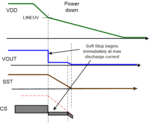 Figure 3-1 Soft-Stop
Operation.
 As Figure 3-2 shows, the results on the TPS23730EVM-093 are identical to the ideal behavior.
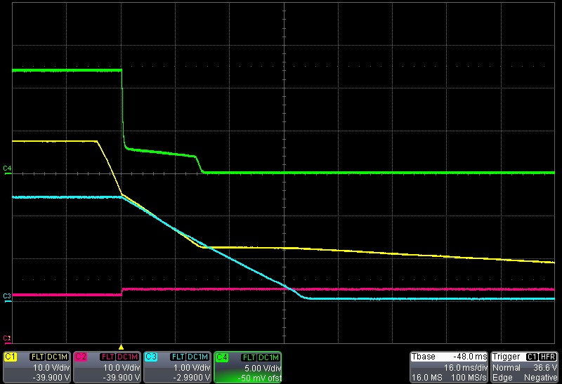 Figure 3-2 PoE Shutdown.
 Ch1: VDD, Ch2: VCC, Ch3: SST, Ch4: VOUT
Soft-stop is also useful in the case of power interruption. As discussed earlier, if the clamp capacitor is precharged from an unsafe shutdown and then power is reapplied, it can cause an overvoltage event on the MOSFET and potentially damage the part. Figure 3-3 shows a brief power interruption with soft-stop.
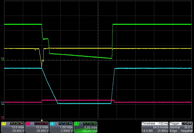 Figure 3-3 PoE Brief Power
Interrupt.
 Ch1: VDD, Ch2: VCC, Ch3: SST, Ch4: VOUT
Finally, a direct comparison follows between a design with soft-stop versus one without. The TPS23730 does allow for the soft-stop to be enabled or disabled. Therefore, a true side-by-side comparison of the feature is demonstrated in Figure 3-4 and Figure 3-5. Figure 3-4 shows the soft-stop feature enabled. The image clearly shows that the VDS voltage of the primary MOSFET (Blue) is well under 150 V. Therefore, 150-V rated MOSFETs are not at risk of damage. Note this is for a 12-V output design. In Figure 3-5, the soft-stop feature is disabled. It is evident that the voltage exceeds 150 V for multiple switching cycles. This would demand high-rated MOSFETs.
 Figure 3-4 Soft-Stop Enabled Full Load
for Primary MOSFETs.
 Ch1: VDD (Yellow), Ch2: Vds P-FET (Pink) Ch3: Vds Primary FET (Blue)
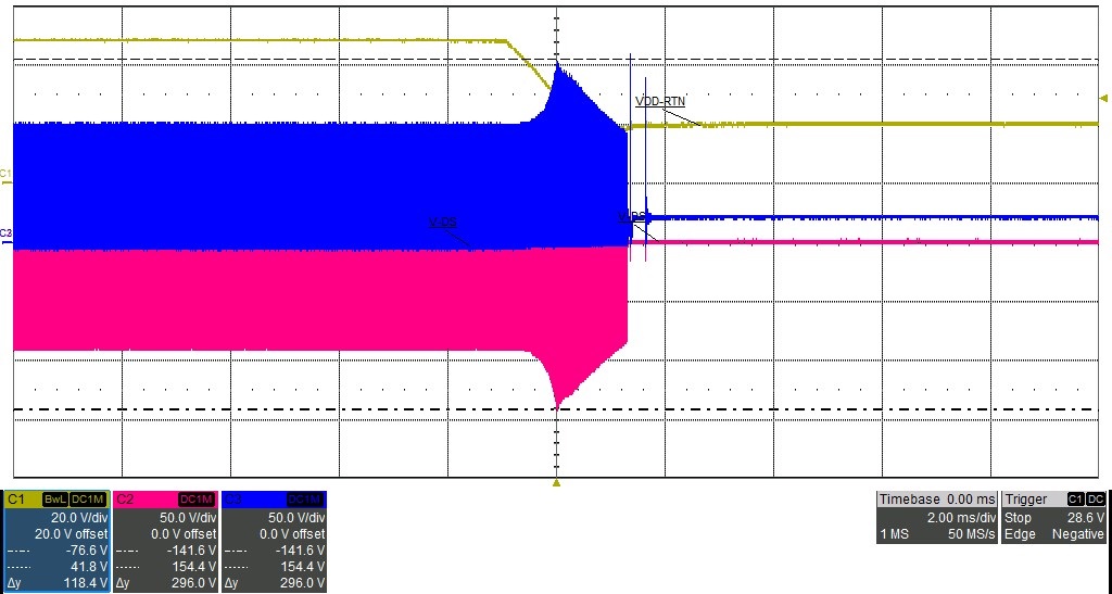 Figure 3-5 Soft-Stop Disabled Full Load
for Primary MOSFETs.
 Ch1: VDD (Yellow), Ch2: Vds P-FET (Pink) Ch3: Vds Primary FET (Blue)
Figure 3-6 and Figure 3-7 show the same conditions for the secondary-side MOSFETs (Q6 and Q8). Figure 3-6 shows the TPS23730EVM-093 with soft-stop enabled. The spike on the series MOSFET (Q8) is only 53.3 V with soft-stop enabled, versus 88.2 V without soft-stop.
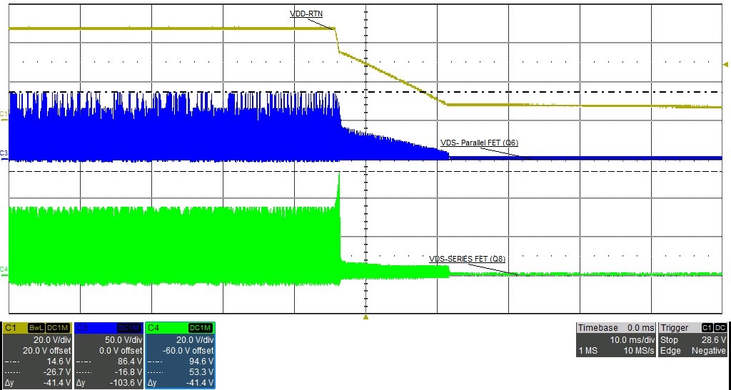 Figure 3-6 Soft-Stop Enabled Full Load
for Secondary MOSFETS.
Ch1: VDD (Yellow), Ch3: Vds Parallel FET (Blue) Ch3: Vds Series FET (Green)
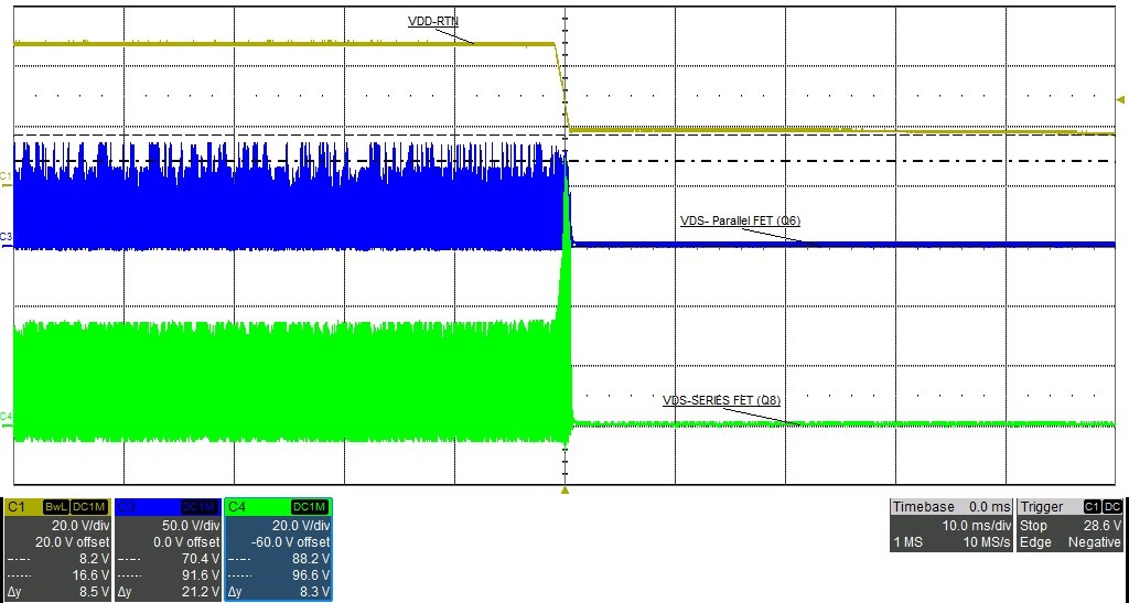 Figure 3-7 Soft-Stop Disabled Full Load
for Secondary MOSFETs.
Ch1: VDD (Yellow), Ch3: Vds Parallel FET (Blue) Ch3: Vds Series FET (Green)
It can also be demonstrated in the no load condition. Figure 3-8 and Figure 3-9 display the primary side of theTPS23730EVM-093 during a shutdown with no load on the output of the DC/DC converter. Figure 3-10 and Figure 3-11 show the secondary MOSFETs for the same conditions.
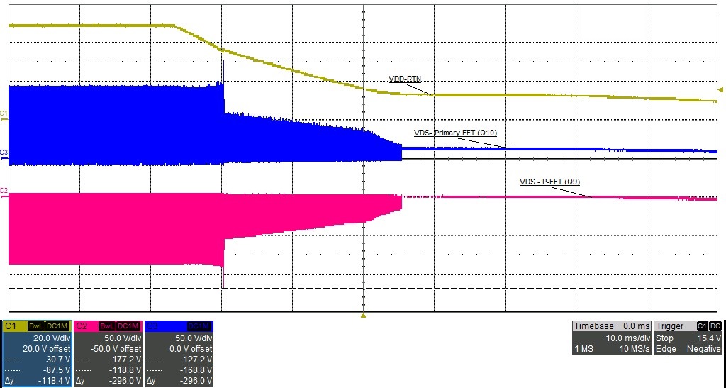 Figure 3-8 Soft-Stop Enabled No Load
Primary MOSFETs.
Ch1: VDD (Yellow), Ch2: Vds P-FET (Pink) Ch3: Vds Primary FET (Blue)
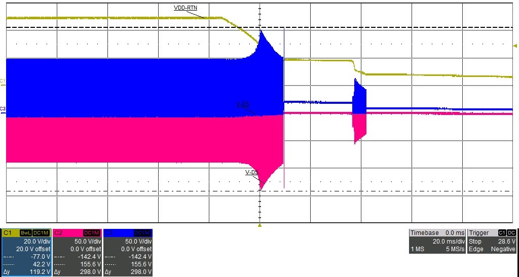 Figure 3-9 Soft-Stop Disabled No Load
Primary MOSFETs.
Ch1: VDD (Yellow), Ch2: Vds P-FET (Pink) Ch3: Vds Primary FET (Blue)
 Figure 3-10 Soft-Stop Enabled No Load
Secondary MOSFETs.
Ch1: VDD (Yellow), Ch3: Vds Parallel FET (Blue) Ch3: Vds Series FET (Green)
 Figure 3-11 Soft-Stop Enabled vs.
Disabled Full Load for Secondary MOSFETs.
Ch1: VDD (Yellow), Ch3: Vds Parallel FET (Blue) Ch3: Vds Series FET (Green)