SLVAEY9 October 2020 TPS23730 , TPS23731 , TPS23734
2 Background
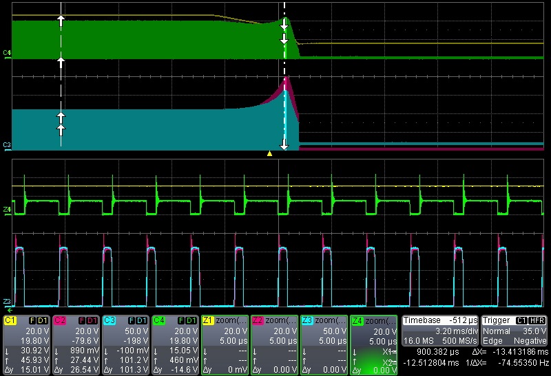
When the input power is removed, the input voltage rails gradually decrease as the input bulk capacitor is discharged. The converter will remain on as the input voltage decreases to its minimum threshold. As the input voltage decreases, the converter increases the duty cycle to compensate. This leads to shorter and shorter off times, and the voltage across the clamp capacitor approaches higher values since the transformer is being reset so quickly. The end result is oscillations and overvoltages that could potentially damage the MOSFETs. Figure 2-1 illustrates these principles.
 Figure 2-1 Active Clamp Forward Shutdown
Sequence Without Soft-Stop.
 Additionally problematic, if a brief power interruption occurs during the next power up, the clamp capacitor will be precharged, which could cause the transformer to saturate. This causes severe stress on the switching components. In this case, the N-FET on the primary side of the transformer and the secondary sync FET (Q3) are at risk. This is explained in more detail in the Line Undervoltage Protection section of the UCC2897A Advanced Current-Mode Active-Clamp PWM Controller Data Sheet.
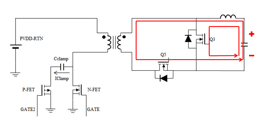
Another case during shutdown is when the converter stops prematurely because the controller has an undervoltage lockout (UVLO). If this threshold is reached when the output voltage is too high, the risk of “backdrive” becomes possible. Backdrive is when the output voltage is high enough to turn on the MOSFET on the secondary side, and this results in energy being driven from the secondary to the primary. The output voltage turns on the gates of both secondary MOSFETs, not at the same time but they eventually are both ON at the same time. Since both MOSFETs are ON, there is approximately 0 V across the transformer secondary inductance.
 Figure 2-2 Light Load Shutdown When Both
MOSFETs are ON.
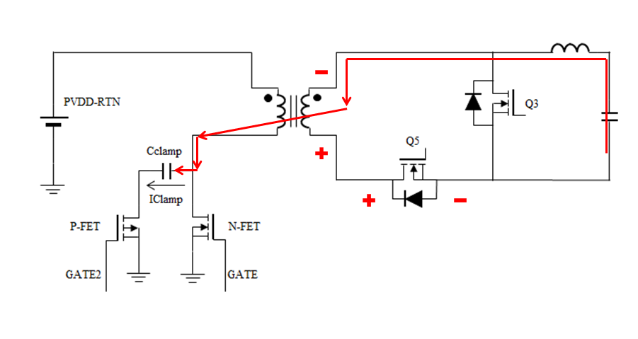
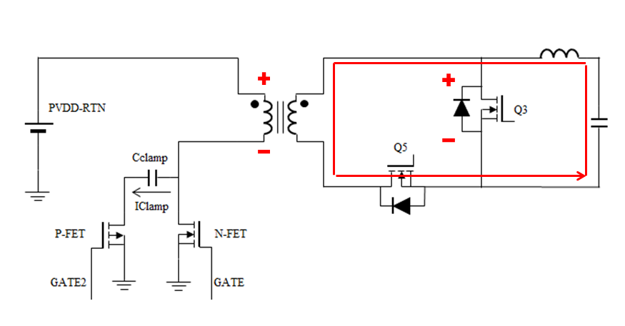
 There are now two current paths on the output. The total VOUT discharge current builds up in the inductance, and a fraction of the discharge current flows through the magnetizing inductance of the transformer. After a short time, the inductor current becomes very high. Over time, the output voltage is dropping so both ends of the secondary goes down. This leads to both MOSFETs turning off. However, the transformer magnetizing current has to be maintained, so it gets transferred to the primary side. This is possible because the series synchronous MOSFET (Q5) is turning off, generating a reverse polarity on the transformer. This forces current through the primary clamp capacitor, and also consequentially, this turns on the parallel synchronous MOSFET (Q3).
 Figure 2-3 Light Load Shutdown When Q5 Turns
OFF.
  Figure 2-4 Light Load Shutdown When Q3 Turns
OFF.
 This pattern continues until the energy in the circuit is too low to turn on the MOSFETs. In this case, the design may require a 200-V (instead of 150 V) rating with avalanche rating for the N-FET and ≥ 100 V (instead of 60 V) (example: 12-V application) rating for Q5 (in Figure 1-1). This is higher BOM cost. The soft-stop feature reduces or eliminates these spikes, thus leading to lower BOM cost.