SLVAFE4 june 2023 TLC6983
2.1 Ghosting
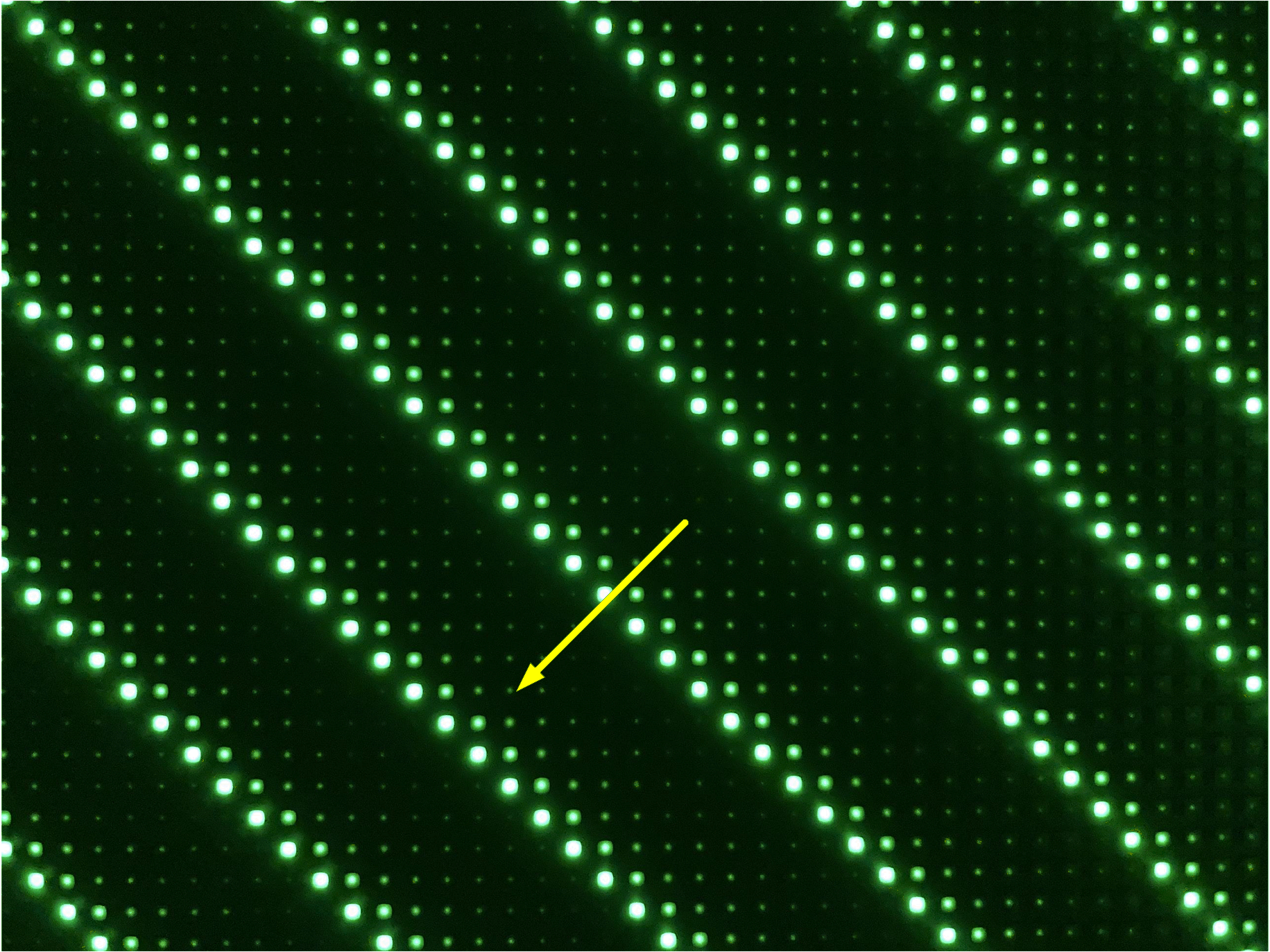
Ghosting is a common issue in NPP LED display applications. Ghosting effect means some LED are lighted up when they do not need to be lighted. The ghosting effect is even more pronounced using the left or right slash grid test pattern. Generally, there are two kinds of ghosting, upside ghosting and downside ghosting shown in Figure 2-1 and Figure 2-2.

Figure 2-1 Upside-ghosting

Figure 2-2 Downside-ghosting
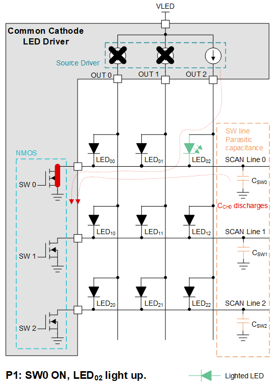
The main cause of upside ghosting is the built up charge in the parasitic capacitance on SWn when transitioning between scan lines, the parasitic capacitance is charged through the LED causing it to light up when it does not need to be lighted.
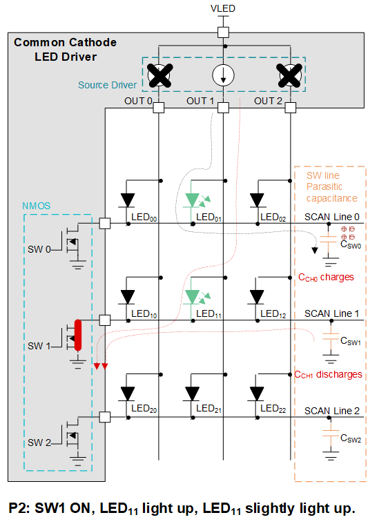
Figure 2-3 and Figure 2-4 shows an example of upside ghosting. During the SW0 turning on, channel 2 outputs current and LED02 is light up. After line switch time, the SW1 turning on, channel 1 outputs current and LED11 is light up. Meantime, the SW0 scan line voltage still keeps low and when the SW1 scan line fully turns on, the channel 1 current may flow through LED01 to the previous scan line causing LED01 to illuminate unexpectedly.

Figure 2-3 Upside Ghosting – 1

Figure 2-4 Upsides Ghosting – 2
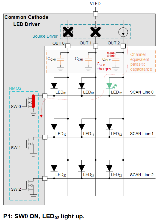
The main cause of downside ghosting is the built up charge in the parasitic capacitance on OUTn when transitioning between scan lines, the charge on the parasitic capacitance will discharge through the LED causing it to light up when it does not need to not be lighted.
Figure 2-5 and Figure 2-6 shows how downside ghosting happens. During the SW0 turning on, channel 2 output current and LED02 is lit up. After line switch time, the SW1 turning on, channel 1 output current and LED11 is lit up. Meantime, the LED12 lights up slightly which is called downside ghosting issue. Since the built up charge in the parasitic capacitance on OUT2 discharges when line switch transition from SW0 to SW1.

Figure 2-5 Downside Ghosting – 1

Figure 2-6 Downside Ghosting – 2