SLVAFJ1 February 2023 TPS2121
3.2 Seamless Switchover from Backup Power (IN2) to Main Power (IN1)
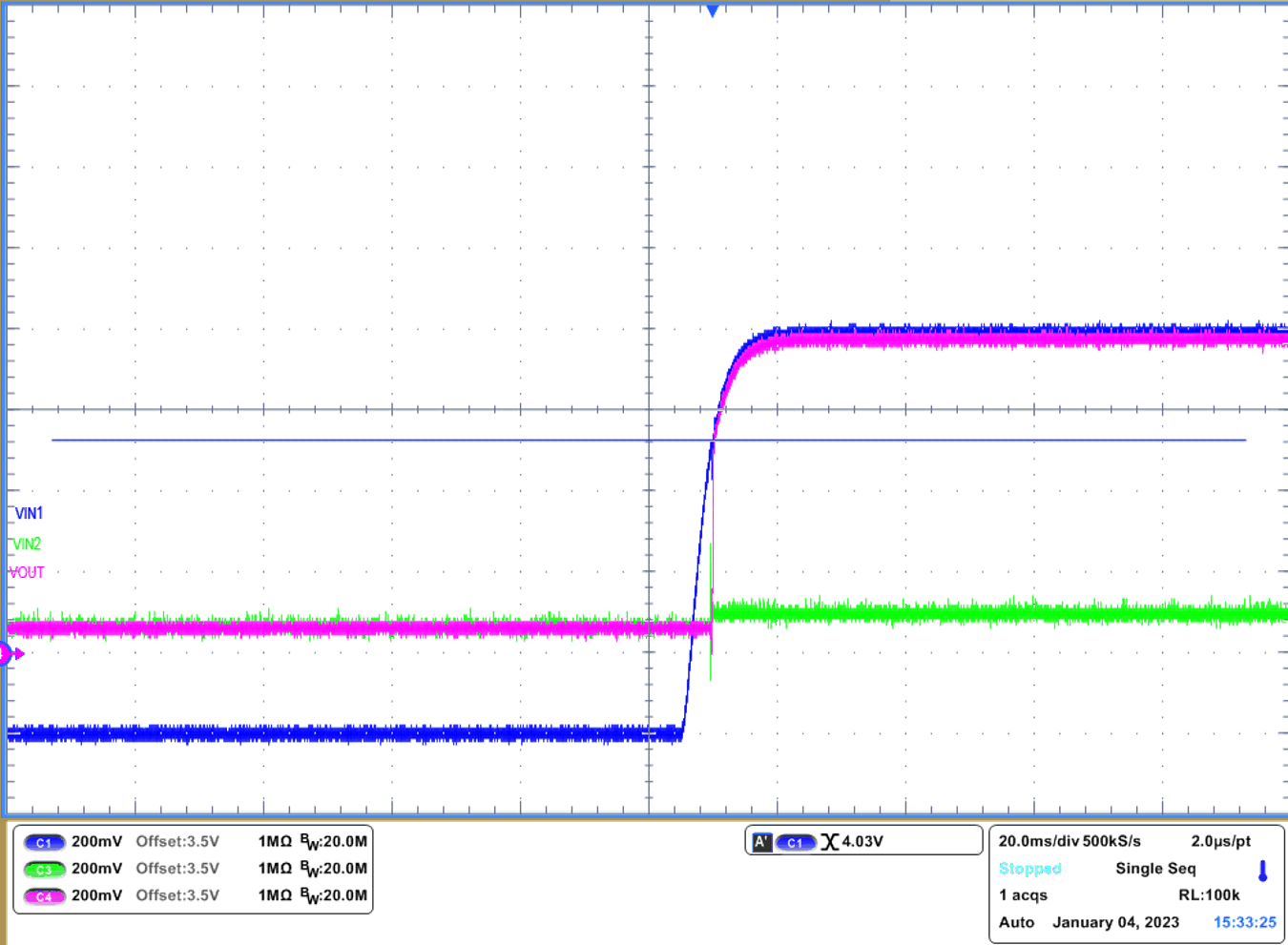
In this scenario, main power source (IN1) has increased above backup power source (IN2), while backup power is supplying downstream system. In this design example, switchover will start automatically when the voltage on IN1 reaches approximately 4.03 V. #GUID-E0CF5828-8CA1-49DB-A4EA-5900AC82F474 shows the switchover in this scenario. Since IN2 is 3.6 V, once IN1 reaches (3.6 V + VCOMP + Hysteresis), TPS2121 will switch over to IN1.
 Figure 3-3 Seamless Switchover from IN2 to IN1
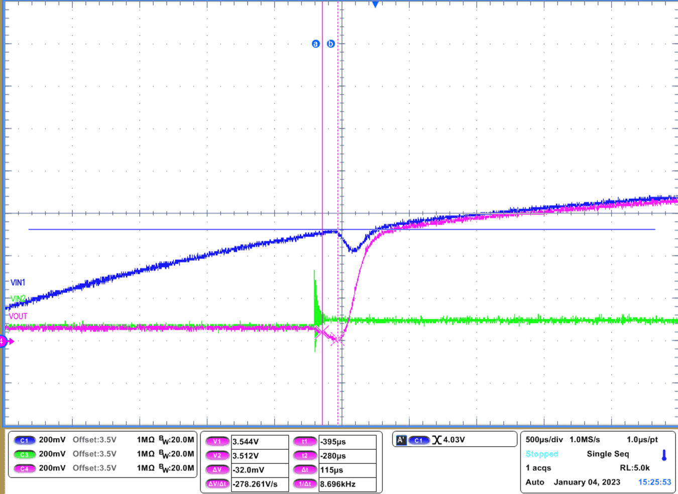
Zooming in on #GUID-DB23475E-7193-4B46-86A0-0C78F7AD2C50, as IN1 increases above 4.03 V, switchover is occurred. It shows IN2 oscillating which causes a delay in choosing a stable supply. Once this oscillation is done, switchover is occurred. VOUT is dropped approximately 32 mV during switchover, Since expected voltage drop during switchover is 31.25 mV. GUID-CEB450AD-E0B9-4DEA-A0E2-09452FE51AC4.html#GUID-7D5C4F9C-E20B-41CF-9A10-AB746E2B839B shows this.
 Figure 3-4 Seamless Switchover from IN2 to IN1