SLVAFR7 February 2024 TPS65219-Q1 , TPS6521905-Q1
2.1 TPS65219-Q1: Pre-Programmed PMIC for 7+ Rail Processors
To power systems similar to AM62x Sitara™ processors, TPS65219-Q1 offers functional safety-capable features without added overhead. Reference designs and technical reference manuals are available for easy set up. With the small 5x5mm package, TPS65219-Q1 has a compact footprint given the excellent powering capabilities. For applications requiring advanced functional safety with an ASIL-B target, consider selecting TPS65224-Q1, which offers functionality with AM62x-Q1 plus advanced functional safety features.
TPS65219-Q1 has three buck converters and four low-dropout regulators optimized to support systems with up to 14+ rails (2x TPS65219-Q1, 7 rails each). Buck1 has the ability to supply up to 3.5A core rail, and Buck2 and Buck3 each support up to 2A. The default output voltages for each buck converter can be selected through I2C interface. With the GPIO pin, multiple TPS65219-Q1 devices can be synchronized for access to additional power rails. Safety features such as undervoltage sensing and temperature thresholds can be set to meet the requirements for the system.
 Figure 2-1 TPS65219-Q1 Simplified
Schematic
Figure 2-1 TPS65219-Q1 Simplified
SchematicAdditionally, TPS65219-Q1 has multi-function pins to adjust to the desired mode. The EN/PB/VSENSE can be configured as a push-button, power-fail comparator input, or a device enable pin. The MODE/RESET pin can be set to MODE for forcing the buck-converters into PWM or permit auto-entry in PFM-mode. The RESET function can force a cold reset and sequence down all enabled rails. The MODE/STBY pin allows the PMIC to operate in a low power mode at light load. These pins are two of the several multi-function pins that make TPS65219-Q1 customizable. Settings can be tested quickly with the available TPS65219 EVM and accompanying user-friendly GUI.
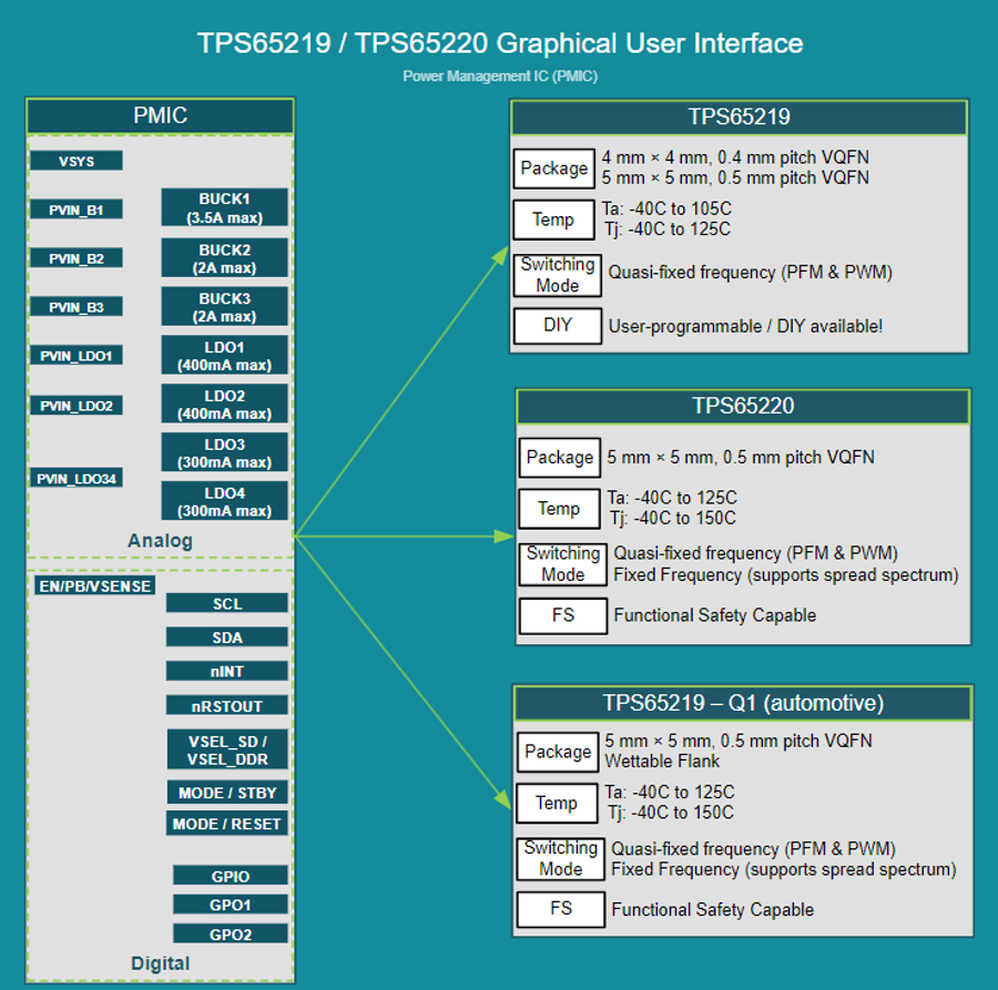
TPS65219-Q1 shares a GUI with the non-automotive version, TPS65219.
 Figure 2-2 TPS65219-Q1 Graphical User
Interface
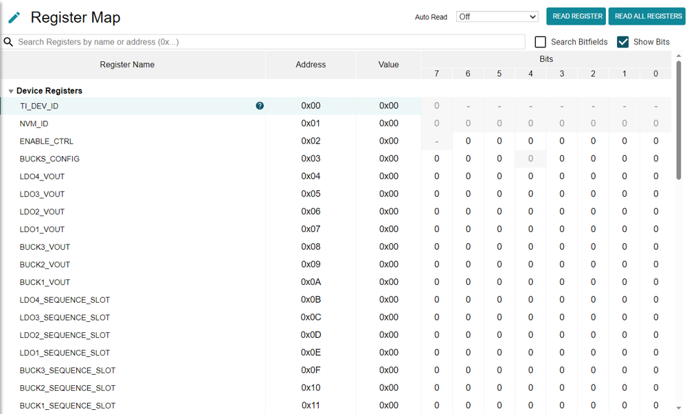
 Figure 2-3 TPS65219-Q1 Register
Map