SLVU793A October 2012 – June 2021 TPS56921
1.3.1 Output Voltage Setpoint
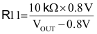
The output voltage of the EVM is set either externally using a voltage divider or internally using the integrated I2C™ interface. The external adjustment of the output voltage is set by the resistor divider network of R10 and R11. R10 is fixed at 10 kΩ. To change the output voltage of the EVM, it is necessary to change the value of resistor R11. Changing the value of R11 can change the output voltage in the range of 0.72 V to 1.48 V. The value of R11 for a specific output voltage can be calculated using Equation 1.
The output voltage can also be set using the optional VID control using the I2C interface. The EVM is designed so that the J3 connector is compatible with the HPA665-001 USB2ANY interface. Using that control and USB2ANY_GUI software allows the output voltage to be programmed to any of 77 preset voltages from 0.72 V to 1.48 V. See the TPS56921 datasheet for a complete description of the available codes. With the software running and the cable attached, confirm the connection by clicking the "Read" button under "Firmware Revision". The firmware revision number will be returned if the connection is good. Set up the interface by selecting "Speed = _400kHz", "Address = _7Bits" and "Pull Ups = OFF" in the "I2C" section. Click on "Set I2C". In the "3.3V/5.0V" section set "3.3V = ON" and "5.0V = OFF". Click on "Set", then click on "Get Status". "GOOD" should be returned for both 3.3 V and 5.0 V. To communicate with the TPS56921EVM-188, in the "Single-Register" section set "I2C Address = 34". In the "Register Address" field, enter the data byte for the voltage you wish to set. Ignore the "Byte to Write" field. Click on "Write" to send the data.
| Code | Binary | VOUT | Code | Binary | VOUT | Code | Binary | VOUT |
|---|---|---|---|---|---|---|---|---|
| 0 | 0000000 | 0.720 | 26 | 0011010 | 0.980 | 52 | 0110100 | 1.240 |
| 1 | 0000001 | 0.730 | 27 | 0011011 | 0.990 | 53 | 0110101 | 1.250 |
| 2 | 0000010 | 0.740 | 28 | 0011100 | 1.000 | 54 | 0110110 | 1.260 |
| 3 | 0000011 | 0.750 | 29 | 0011101 | 1.010 | 55 | 0110111 | 1.270 |
| 4 | 0000100 | 0.760 | 30 | 0011110 | 1.020 | 56 | 0111000 | 1.280 |
| 5 | 0000101 | 0.770 | 31 | 0011111 | 1.030 | 57 | 0111001 | 1.290 |
| 6 | 0000110 | 0.780 | 32 | 0100000 | 1.040 | 58 | 0111010 | 1.300 |
| 7 | 0000111 | 0.790 | 33 | 0100001 | 1.050 | 59 | 0111011 | 1.310 |
| 8 | 0001000 | 0.800 | 34 | 0100010 | 1.060 | 60 | 0111100 | 1.320 |
| 9 | 0001001 | 0.810 | 35 | 0100011 | 1.070 | 61 | 0111101 | 1.330 |
| 10 | 0001010 | 0.820 | 36 | 0100100 | 1.080 | 62 | 0111110 | 1.340 |
| 11 | 0001011 | 0.830 | 37 | 0100101 | 1.090 | 63 | 0111111 | 1.350 |
| 12 | 0001100 | 0.840 | 38 | 0100110 | 1.100 | 64 | 1000000 | 1.360 |
| 13 | 0001101 | 0.850 | 39 | 0100111 | 1.110 | 65 | 1000001 | 1.370 |
| 14 | 0001110 | 0.860 | 40 | 0101000 | 1.120 | 66 | 1000010 | 1.380 |
| 15 | 0001111 | 0.870 | 41 | 0101001 | 1.130 | 67 | 1000011 | 1.390 |
| 16 | 0010000 | 0.880 | 42 | 0101010 | 1.140 | 68 | 1000100 | 1.400 |
| 17 | 0010001 | 0.890 | 43 | 0101011 | 1.150 | 69 | 1000101 | 1.410 |
| 18 | 0010010 | 0.900 | 44 | 0101100 | 1.160 | 70 | 1000110 | 1.420 |
| 19 | 0010011 | 0.910 | 45 | 0101101 | 1.170 | 71 | 1000111 | 1.430 |
| 20 | 0010100 | 0.920 | 46 | 0101110 | 1.180 | 72 | 1001000 | 1.440 |
| 21 | 0010101 | 0.930 | 47 | 0101111 | 1.190 | 73 | 1001001 | 1.450 |
| 22 | 0010110 | 0.940 | 48 | 0110000 | 1.200 | 74 | 1001010 | 1.460 |
| 23 | 0010111 | 0.950 | 49 | 0110001 | 1.210 | 75 | 1001011 | 1.470 |
| 24 | 0011000 | 0.960 | 50 | 0110010 | 1.220 | 76 | 1001100 | 1.480 |
| 25 | 0011001 | 0.970 | 51 | 0110011 | 1.230 | >76 | >1001100 | Illegal / Special |