SLVUC15 March 2021 TPS7H4001-SP
2.1 Importing the TPS7H4001-SP WCA Model into PSpice projects
- Open the Capture application from Cadence - v17.2.0 or above.
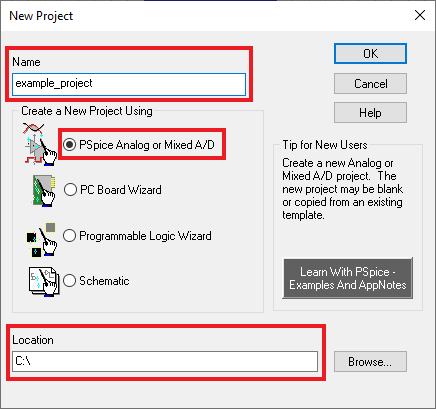
- Click File → New → Project.
- Enter a project name and location, choose PSpice Analog or
Mixed A/D from the options, and then click OK.
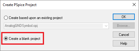
- When the Create Pspice Project dialogue box appears,
select the Create a blank project option and click OK.
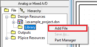
- A new project is created and the
project window displays. Right click the Library folder and select Add
File.
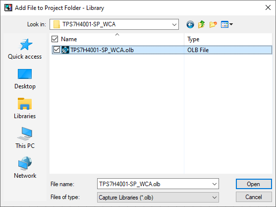
- Choose the tps7h4001-sp_wca.olb file from the downloaded
model, add to the dialogue box, and click Open. This adds the part symbol
to the project.
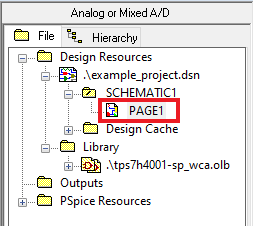
- In the project navigation window,
open PAGE1 under the SCHEMATIC1 folder below the .dsn
file.
- Select
Place → Part to open the Place Part window. Click
on the square icon shown in the following image to add libraries to the project.
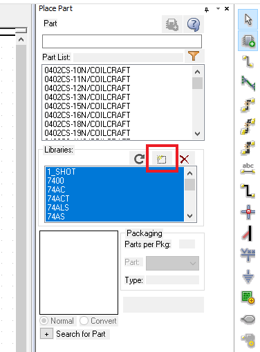
- If the default library files of PSpice do not appear in the Libraries window as shown above in blue, they can be located in the installation directory. To add them, highlight them all and click Open. (Default installation directory location: C:\Cadence\SPB_17.2\tools\capture\library\pspice)
- In the Part search field, type
TPS7H4001-SP_WCA and select the model in the Libraries window.
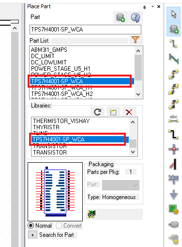
- In the Part List window, double-click on
TPS7H4001-SP_WCA and place it by clicking the cursor on PAGE1
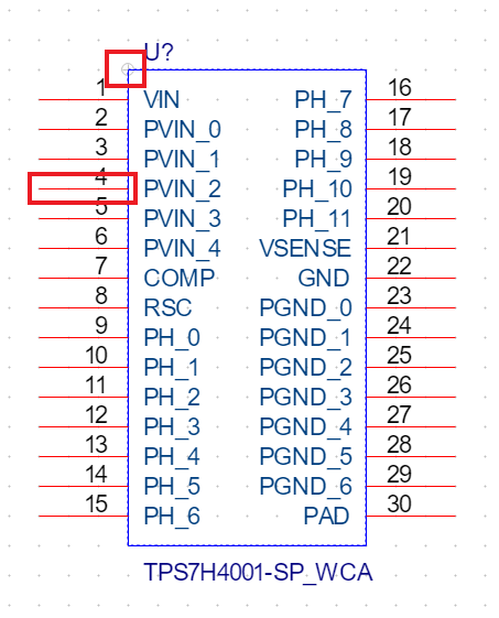
to place the part. Once the part is placed, the symbol can be edited by
selecting the part, right-clicking, and choosing Edit Part.
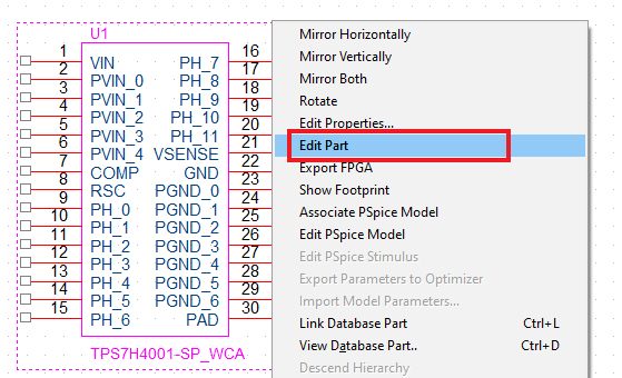
- The part can be resized and pins can
be moved to more convenient positions by clicking and dragging them.
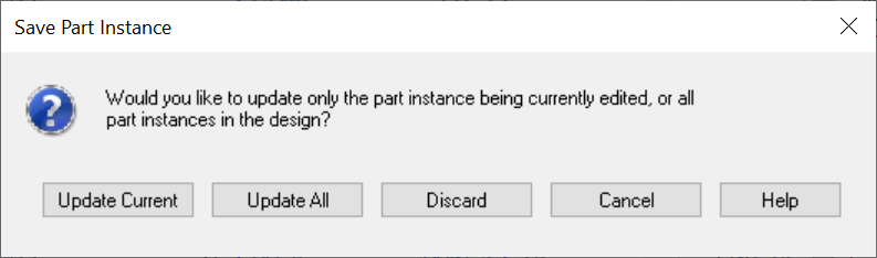
- After editing the part, close the tab to save changes. Choose
Update Current in the pop-up.
- The model contains multiple controllable parameters that can be displayed near the part on the schematic to make them easier to view and alter. The default values for these parameters can be found in Section 1.1.
- To make
the parameters visible, double-click the part to open the properties table. If
it appears to be transposed compared to the image shown below, clicking
Pivot will reorient it.
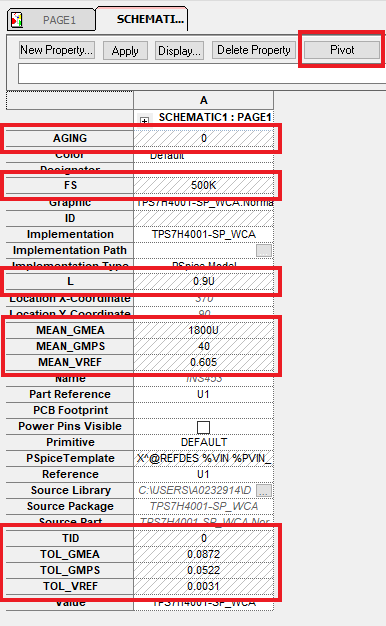
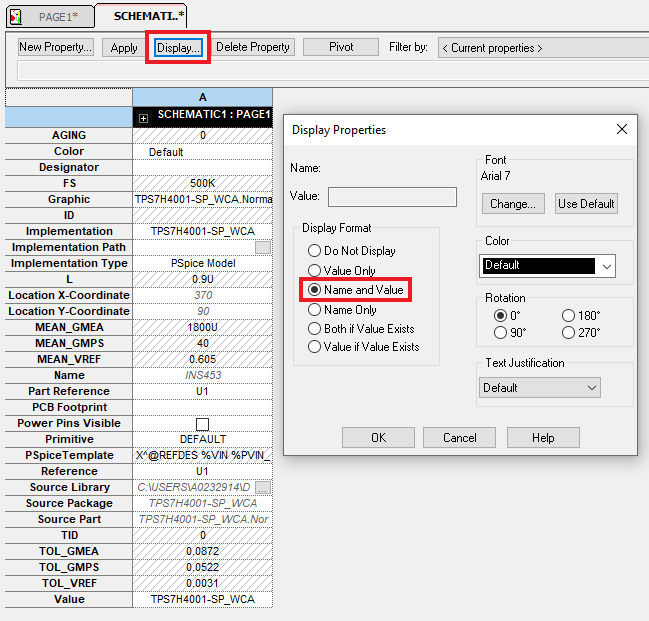
- Select all the parameters highlighted
in the previous image and click the Display button. In the pop-up, select
Name and Value and click OK.
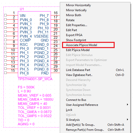
- Now, the part must be associated with the netlist. Select the
part, right-click, and then choose Associate Pspice Model.
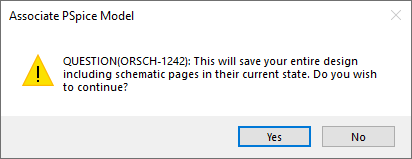
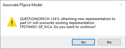
- Two pop-ups will appear to confirm the operation. Click
Yes for both.
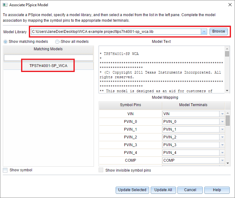
- In the Associate Pspice Model dialogue box, choose the
netlist file (***.lib), select the model, and click Update All.
- A pop-up will appear with successful update message. Click
OK.
- Add the remaining
components to complete the schematic as shown in the schematic below.
 Figure 2-1 Model
Schematic
Figure 2-1 Model
Schematic