SLVUC15 March 2021 TPS7H4001-SP
2.2 Using Pspice for TI
- Download, install, and open Pspice® for TI.
- Open an existing project, or click on File→New→Project to create a new project.div
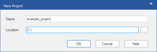
- If creating a new project, enter
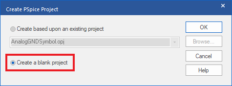
a project name and location and click OK. Then select the Create a
blank project option and click OK again. A new project
will be created and the project window appears.
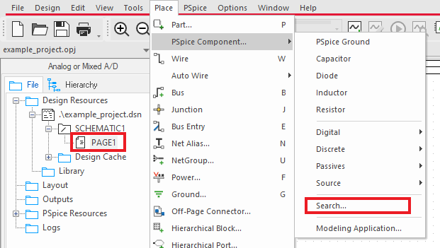
- Open the schematic page where the
part will be placed ("PAGE1" in the example below) and then open the PSpice
Part Search window by selecting Place→PSpice
Component→Search
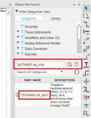
- Type
tps7h4001-sp_wca into the search field and press the enter key to
display the search results. Double-click on the WCA model that appears in the
search results window and then click in the schematic page to place the
part.
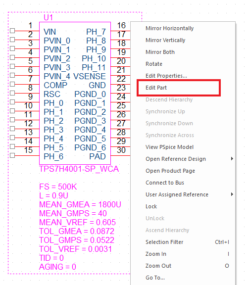
- Once the part is placed, the symbol
can be edited by selecting the part, right-clicking, and choosing Edit
Part.
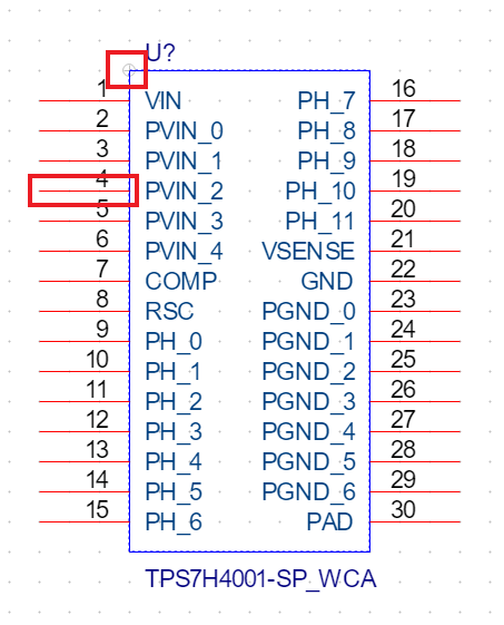
- The part can be resized and pins
can be moved to more convenient positions by clicking and dragging
them.
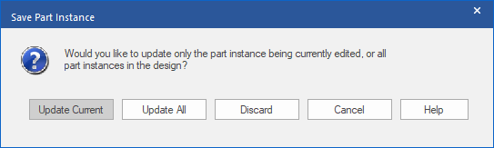
- After editing the part, close the
tab to save changes. Choose Update Current in the pop-up.
- To make the parameters visible,
double-click the part to open the properties table. If it appears to be
transposed compared to the image shown below, clicking Pivot will
reorient it.
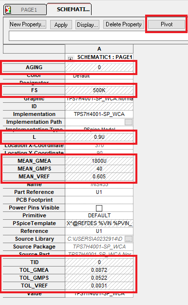
- The model contains multiple controllable parameters that can be displayed near the part on the schematic to make them easier to view and alter. The default values for these parameters can be found in Section 1.1.
- Select all the parameters highlighted above and click the Display button. In the pop-up, select Name and Value and click OK.
- Close out of the Property Editor window. The parameters should now be displayed underneath part on the schematic page and their values can be altered by double-clicking on them.
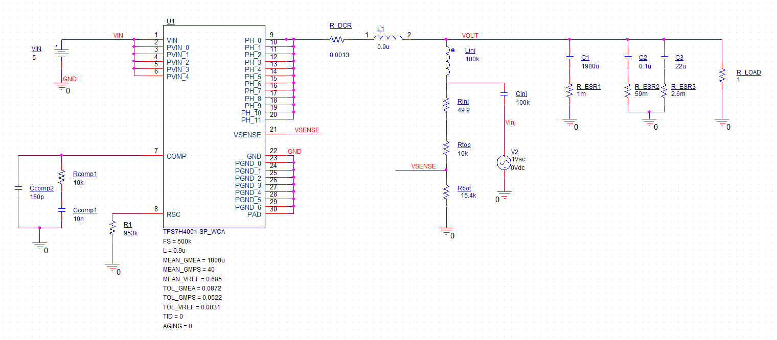
- Add the remaining components to
complete the schematic as shown below.