SLVUC77 June 2021 DRV8770
3.1 EVM connection
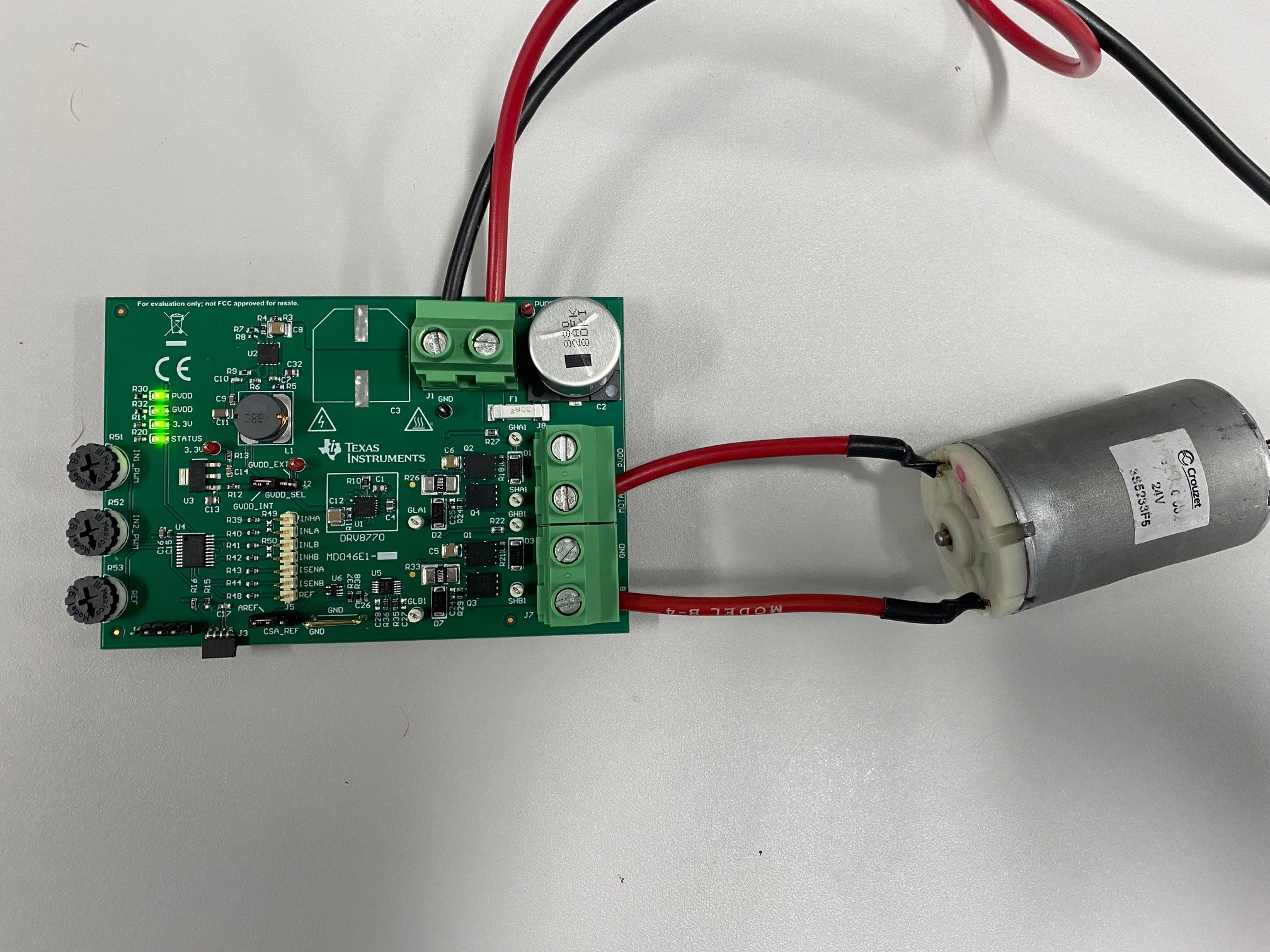
The EVM to motor connections to power supply and motor in Figure 3-1. If the power is correctly being distributed to the board and the MCU is active, all of the four LEDs on the top left should be ON. If one of the LEDs is not ON, then the board will not work. Further debugging will be needed to figure out what is wrong with the board. IF assistance is needed from TI, feel free to post a question to the E2E forum.
Since the DRV8770 can independently drive each half-bridge, two motors can be driven unidirectionally in either low-side or high-side configurations (MOTx to PVDD or MOTx to GND). If bi-directional motor control is required, then the motor should be connected between MOTA and MOTB.
If the user wants to bypass the on-board 12-V buck converter used for the DRV8770 supply, the shunt on J2 can be placed between the middle pin and GVDD_EXT. The external power supply will be connected on the "GVDD_EXT" red test point near J2. Make sure the external GVDD voltage does not exceed the maximum ratings of the DRV8770.
 Figure 3-1 EVM Power Supply and Motor
Connections