SLVUCO5 March 2023 TPS7H1111-SEP , TPS7H1111-SP
PRODUCTION DATA
4 Adjustable Operation
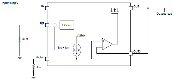
The nominal output voltage for the TPS7H1111-SEP is configured using equation VSS_SET = VOUT = ISET x RSET. Therefore, RSET = VSS_SET / ISET = 1.8 V / 100 μA = 18 kΩ. ISET is determined by RREF, and is designed to be 100 uA using a precision 12 kΩ resistor. See Figure 4-1 for block diagram. See Figure 7-1 for RSET (R8), and RREF (R9) connectivity. See SLVSFT8 for more detailed information.
 Figure 4-1 Simplified Schematic to Configure
Output Voltage
Figure 4-1 Simplified Schematic to Configure
Output VoltageIt is also important to note that the TPS7H1111-SEP utilizes an adjustable power good PG output threshold FB_PG. When changing the output voltage, a suitable voltage divider needs to be set on the FB_PG pin in order for the LDO to assert PG when appropriate threshold achieved. Additionally when PG is asserted, this turns off internal fast charge circuit that is part of the soft start. Thus, setting appropriate divider is important for proper startup. See SLVSFT8 for more detailed information.