SLVUCR9B August 2023 – January 2024 TPS2HCS10-Q1
3.1.1 Command Center View
The Command Center View is meant to provide quick access to some of the common configuration and run-time settings of the attached high-side switch. The user has the ability to turn on/off individual channels, plot/graph ADC readings such as current sense, configure PWM settings, and put the device into several diagnostic states. Note that by default, the device is set to auto-persist changes made in the GUI. This means that when the user changes a setting on the interface, the command is sent through USB and translated as a SPI command to persist to the high-side switch.
To enable/disable individual channels, simply click the desired channel in the Channel Enable box. This causes the corresponding channel to turn on and conduct current if there is a load on the output. Likewise, to enable current sense/graphing for a particular channel, click the desired channel on the Graph Settings box. This causes the GUI to start a polling thread that periodically reads the high-side switch of the current sense register. When a channel is enabled for graphing, the microcontroller automatically enables the relevant ADC bits in the register settings.
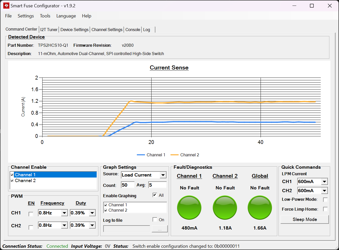 Figure 3-1 Current Sense Graph
Note that by default the device is set to collect and average a specified number of values before plotting them on the graph. The maximum number of samples to collect can be changed through the Count setting and the averaged number of samples can be changed with the Avg setting. In addition to load current, the device can also be configured to graph/report FET temperature and output voltage. This setting is changed through the Source box.
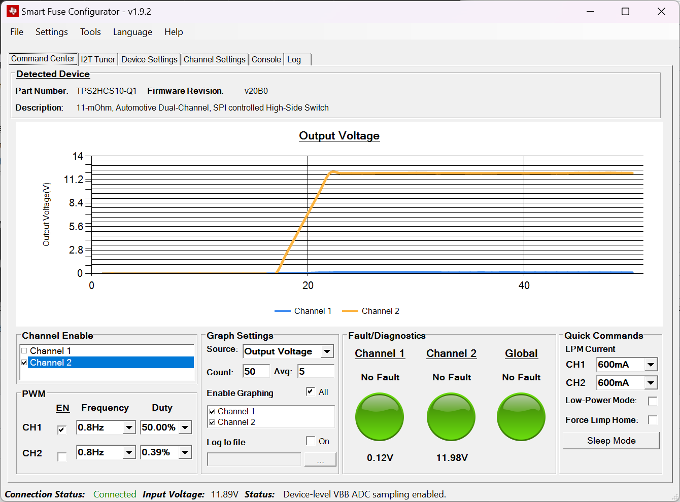 Figure 3-2 Voltage Graphing
The Log to File button gives the user the ability to dump any sense readings to a specified comma separated value (CSV) file. When this box is selected, the program prompts for a location to save and start recording files if that location is valid. The log file is closed/saved if the Log to File button is turned off or if the program is closed.
The Quick Commands box provides various settings/diagnostic commands. The LPM exit current can quickly be configured per-channel and the device can be forced into low-power mode through the Low-Power Mode box. Once in low-power mode, if the load current on a corresponding channel exceeds what is configured in the settings the device exits the low-power mode (or if the low-power mode box is unchecked). Refer to the device data sheet (SLVSGY2) for exact operation behavior for low-power mode.
The Force Limp Home box forces the device to enter a limp home mode state. Generally, external circuitry is designed to trigger the LHI pin of the high-side switch when a system-wide fault occurs, however for evaluation purposes the Force Limp Home box causes the MCU to force trigger the LHI pin of the high-side switch. This causes the device to default to the state configured in the device configuration registers of the high-side switch (see the data sheet for details).
The Sleep Mode button prompts a dialog to put the device in sleep mode. In sleep mode, the device enters an inactive state with minimal power consumption. In this mode, all device configurations are reset to the reset values. The Smart Fuse Configurator software, however, has logic that restores the configured values after sleep mode is exited. By clicking the sleep mode button, a prompt occurs to warn the user about the state change.
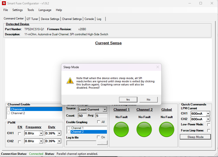 Figure 3-3 Enter Sleep Mode
Once Yes is clicked, the device goes into sleep mode by a SPI write to the corresponding SLEEP register. The device stays in sleep mode until the user clicks OK on the GUI.
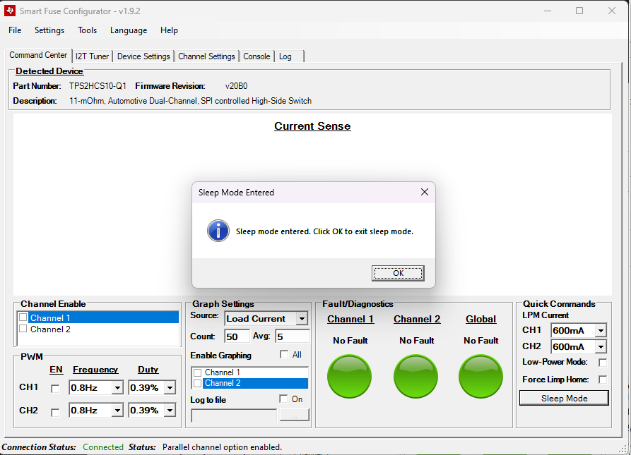 Figure 3-4 Device in Sleep Mode
Once OK is clicked, a dummy write occurs that takes the device out of sleep mode. Once out of sleep mode, the GUI takes the current configuration settings from the GUI and writes them back to the device.
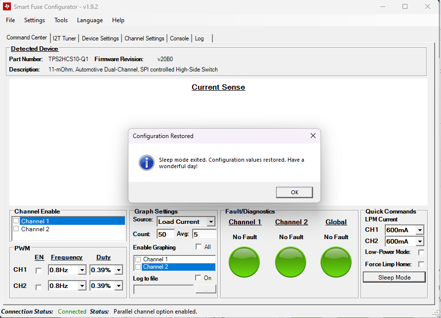 Figure 3-5 Settings Restored