SLYA072 may 2023 TMAG5253
4 Magnet Sensor Placement
The goal of the design presented in this application report, is to have the output range from mid-supply to either the supply or ground rail over the full range of motion like the top middle plot in Figure 4-1. If the output in the default rest-state angle is well above mid-supply and the output rails to the supply with minimal movement like in the left plot, the magnet is too close to the sensor. Conversely, if the output barely changes over the range of movement like the right plot, the magnet is too far away. Yet another possibility is that the sensor sees the same voltage potential at two different angles like in the bottom figure. For a single Hall-element sensing design this is something to avoid as the two angles are indistinguishable to the sensor. For this scenario, consider reorienting the sensor or the magnet.
 Figure 4-1 Output Example Plots
The key bounding constraints for this design are likely to be space and cost, with cheaper and smaller magnets being desired. Small magnets are desired from the standpoint that you have a small controller enclosure filled with other sensors, haptic motors, power converters, wireless transceivers, and processing circuits. Therefore, minimal space is allocated to the trigger and the magnet needs to fit within the trigger. Smaller magnets have less magnetic flux and cheap magnets like ferrite magnets have the least amount of magnetic flux. Consequently, the sensor needs to be near the magnet.
How close the magnet needs to be can be determined through iteration. Fortunately, there are tools for example, TI's Magnetic Sensing Proximity Tool shown in Figure 4-5 that allow the user to test multiple cases before proceeding to bench builds. For the final test iteration, a 3/8-in (9.525-mm) diameter by 1/8-in (3.175-mm) thick cylindrical ceramic-ferrite magnet that fits in the trigger assembly as shown in Figure 4-2 was selected. After clicking Calculate B-Field & Vout, the tool prompts users to enter more magnet information such as in Figure 4-4, if Custom was selected for Magnet Material. In this entry form, relative permeability (μ_r) and coercivity (H_c) are required. These values can be determined from magnet manufacturer specifications and Equation 1.
 Figure 4-2 Trigger Module
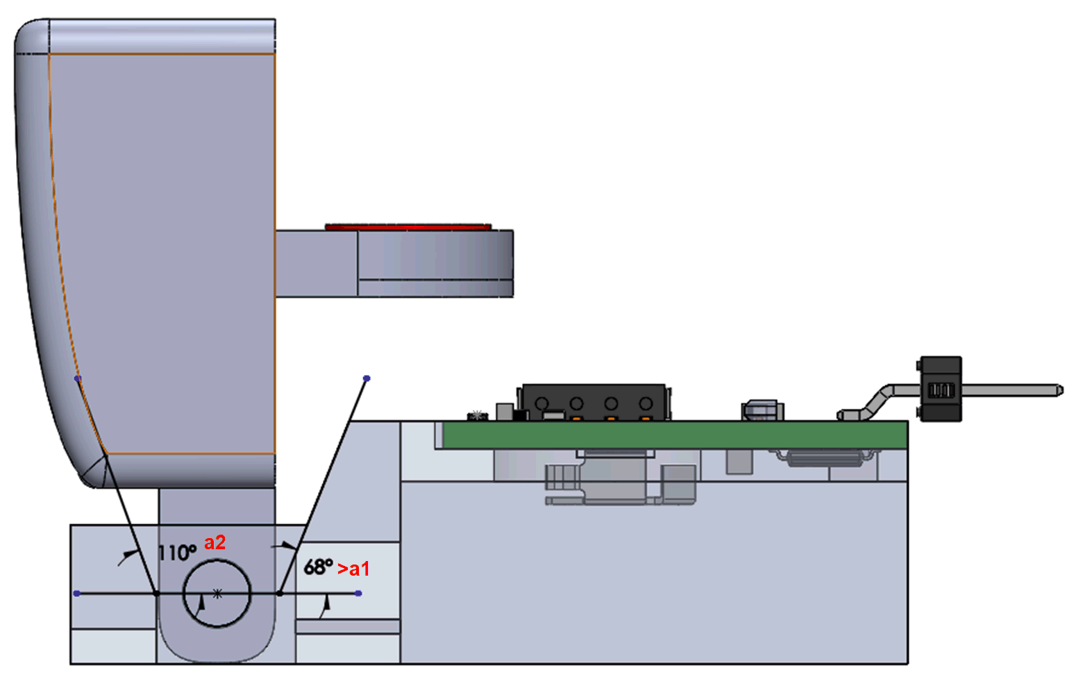
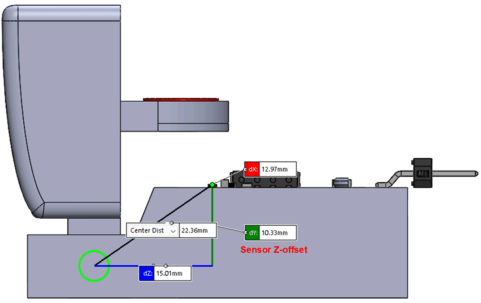
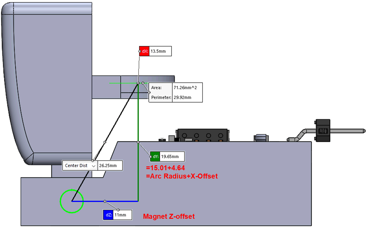
To simplify assessment within the tool, the trigger was reoriented to match the orientation of tool placement specifications. The trigger implementation chosen for this application has a hinge movement that moves between a range of angles that can be specified in the tool entry fields a1 and a2 as indicated in Figure 4-3. Based on ergonomics, a range between 65° and 110° was set. Aside from angle range, Figure 4-3 indicates that multiple additional specifications were required for proper evaluation. These specifications correspond to dimensions outlined in Figure 4-5. Arc Radius, Sensor Z-Offset, and Magnet Z-Offset are all relative to the hinge origin, while X-offset and Y-offset are relative to the device origin. Upon specifying relative magnet and sensor locations, a device can be selected. In this case the TMAG5253 is considered, because this device is a lower power device that can be enabled and disabled.
 Figure 4-3 Tool Input
 Figure 4-4 Magnet Entry


Figure 4-5 Magnet Device Relative Placement
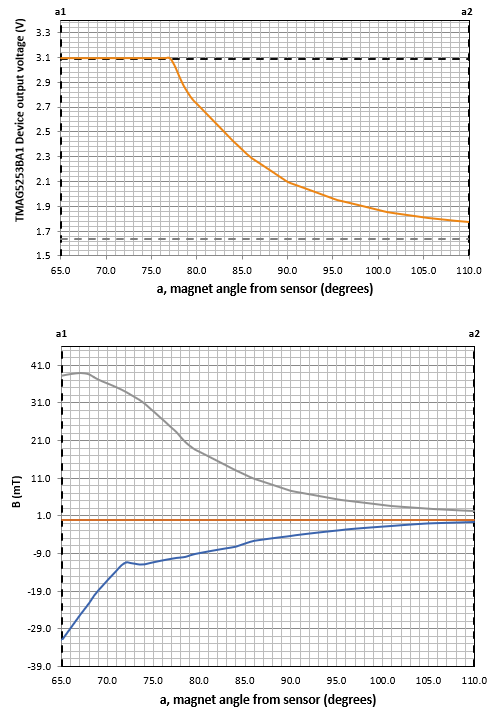
Simulation results in Figure 4-6 indicate that this design is outside the desired design goal since the output is not linear and the output rails to the supply prematurely. At this point there are a few options. These options include modifying various mechanical parameters, modifying the magnet, or trying a different sensitivity variant of the device. Spacing the magnet further away from the device decreases the field observed at angles closer to a1; however, that pulls the device into a region where larger angles near a2 have subtle to no difference. A less sensitive device with a broader measurement range can be used. However, since there is some flexibility in mechanical design, the lower angle bound was reduced to around 75°. Linearity for this particular range and type of motion is difficult to achieve and the output values between 79° and 110° do not repeat or lead to aliasing; therefore, advancing to the next stage of development is reasonable.
 Figure 4-6 Simulation Output