SLYT803B october 2020 – october 2020 BQ24610 , BQ25713 , BQ25790 , LM66100 , LM74700-Q1
- 1
- 1 Introduction
- 2 Understanding Battery Packs
- 3 Stackability Requirements for Battery Packs
- 4 A Multibattery Management System Design
- 5 Battery Charging
- 6 Battery Gauging and Protection
- 7 DC-to-DC Converter or Controller Stage (Boost or Buck-boost Stage)
- 8 ORing Control
- 9 Load Sharing
- 10Conclusion
- 11References
- 12Related Web Sites
2 Understanding Battery Packs
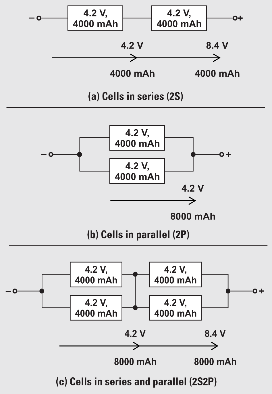
A single cell is a electrochemical source of electrical potential, or voltage. Its size and chemical type determine the cell’s nominal capacity and voltage rating, respectively. Battery packs achieve the desired operating voltage by connecting several cells in series; each cell adds its voltage potential to derive the total terminal voltage. A parallel connection of cells attains higher capacity by adding up the total ampere-hour ratings of the cells. Some packs comprise both series and parallel connections. For example, a battery pack with four cells in series and two cells in a parallel configuration is called 4S2P (4 series, 2 parallel); similarly, a 5S4P configuration has five cells in series and four cells in parallel.
Figure 1a shows a battery pack with two 4.2-V lithiumion (Li-ion) cells in series (2S), to produce a nominal voltage of 8.4 V. Adding cells in a string only increases the voltage; the capacity remains the same. For higher currents, one or more cells can be connected in parallel, as shown in Figure 1b. The combined series and parallel configuration shown in Figure 1c enables design flexibility and achieves the required voltage and current ratings for an ultrasound scanner application with a standard cell size.
 Figure 1 Voltage and Capacity
Scaling for a Li-ion Battery