SLYT826 April 2022 DRV5055 , DRV5056 , TMAG5170 , TMAG5273
3 Effect of device package type on sensed magnetic flux density
The magnetic flux density sensed by a Hall-effect sensor depends on the magnet dimensions, magnet material, and distance from the magnet to the sensing element within the Hall-effect sensor package. The location of the sensing element within the package can affect magnetic flux density readings, especially when the magnet is close to the sensor.
Hall-effect sensor device data sheets usually include the location of the sensing element within the package, as this location can vary for each device and its package types.
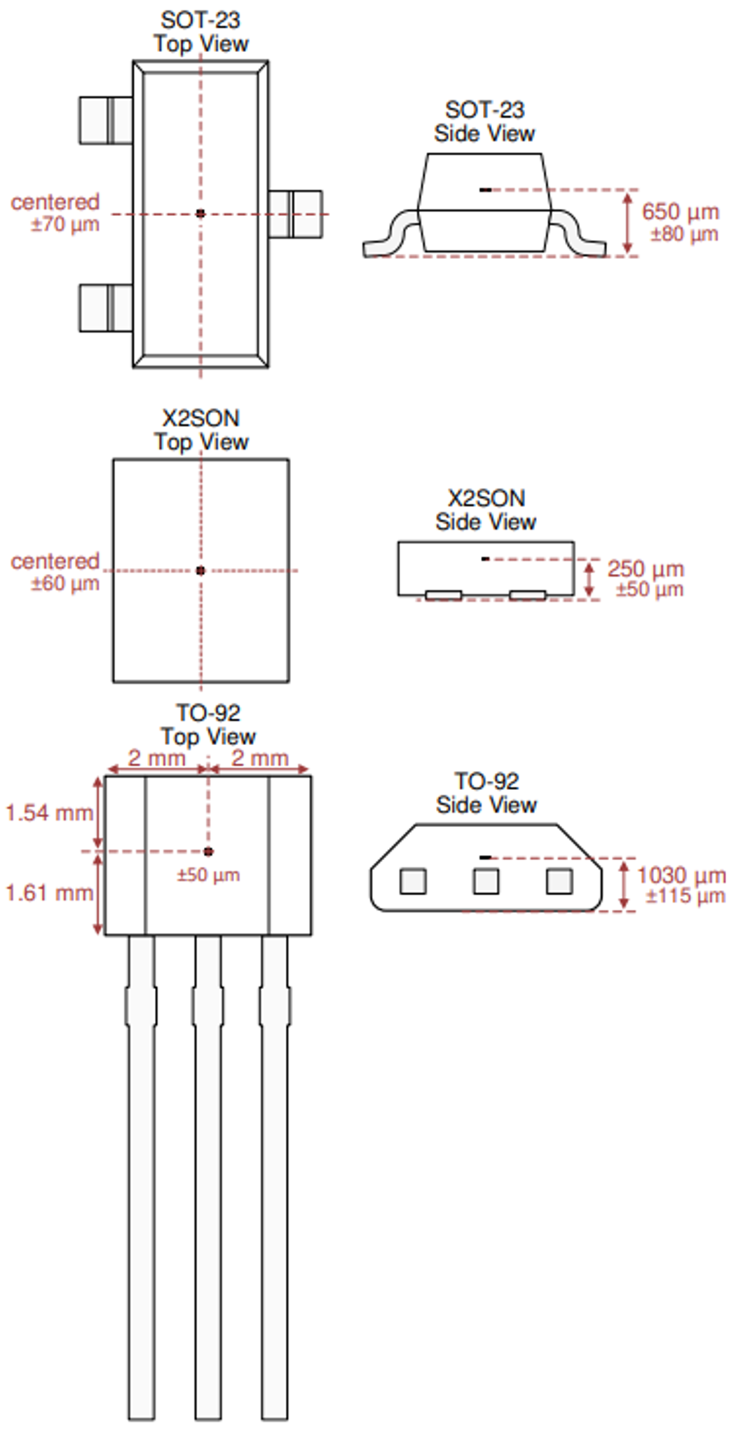
Figure 3-1 shows the location of the sensing element within a device’s SOT-23 and extra-small outline no-lead (X2SON) surface-mount package options. If applying a magnet 5 mm above the PCB, the distance from the magnet to the sensing element would be smaller in the SOT-23 package (4.35 mm) than in the X2SON package (4.75 mm), giving the SOT-23 package a larger magnetic flux density magnitude than the X2SON package.
On the other hand, if you applied the magnet 5 mm below the PCB, the magnet-to-sensing element distance would be larger for the SOT-23 package (5.65 mm) than for the X2SON package (5.25 mm), thereby resulting in a smaller magnetic flux density magnitude for the SOT-23 package.
 Figure 3-1 Example sensing locations in
SOT-23 and X2SON packages.
Figure 3-1 Example sensing locations in
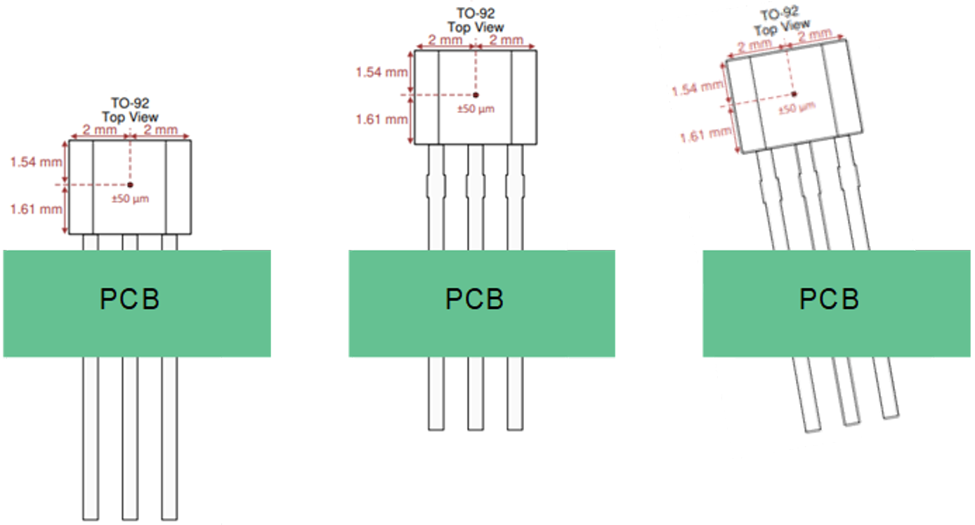
SOT-23 and X2SON packages.With through-hole packages like the TO-92 package shown in Figure 3-2, the location of the sensing element also depends on the height of the device installation with respect to the PCB surface. In Figure 3-2(b), the installation is such that the device’s sensing location is further from the PCB surface than the sensor installation in Figure 3-2(a). As a result, the two sensor installations would measure different magnetic flux densities.
In addition to the variation in results from different device installation heights, the angle of sensor placement affects readings as well. In the installation shown in Figure 3-2(c), the sensor is bent slightly toward the left compared to the installation in Figure 3-2(b), which would result in different magnetic flux densities. Bending the sensor to the right, forward or backward would also affect sensor readings. Given the variation that can result from the device installation height and angle, through-hole Hall-effect sensors require careful installation.
Using device spacers to control the package height will help eliminate the variability in sensor readings. Another option replaces through-hole out-of-plane linear Hall-effect sensors with surface-mount 1D in-plane sensors or 3D sensors.
 Figure 3-2 Variations in though-hole
sensor placement: Device installed closer to PCB(a); Device placed further from
PCB with no bending (b); Device placed further from the PCB and bent to the
left(c).