SLYT826 April 2022 DRV5055 , DRV5056 , TMAG5170 , TMAG5273
1 Introduction
Many systems require a solution to translate the mechanical position of linearly moving components into electrical signals so that the electronics in the system can react to the component’s position. Contact-based mechanical solutions such as potentiometers traditionally accomplished this translation by converting mechanical positions into an output voltage.
For example, a cordless power drill uses a potentiometer to translate the displacement position of the trigger to an output voltage that adjusts its speed accordingly, while a video game controller joystick uses two potentiometers to translate the x and y position of the joystick into output voltages for the x and y axes.
Because of their contact-based operation, potentiometers typically wear down faster than non-contact-based alternatives. This reduction in reliability and system lifetime is further exacerbated if the potentiometer is exposed to vibrations or external influences such as moisture, dirt or other debris.
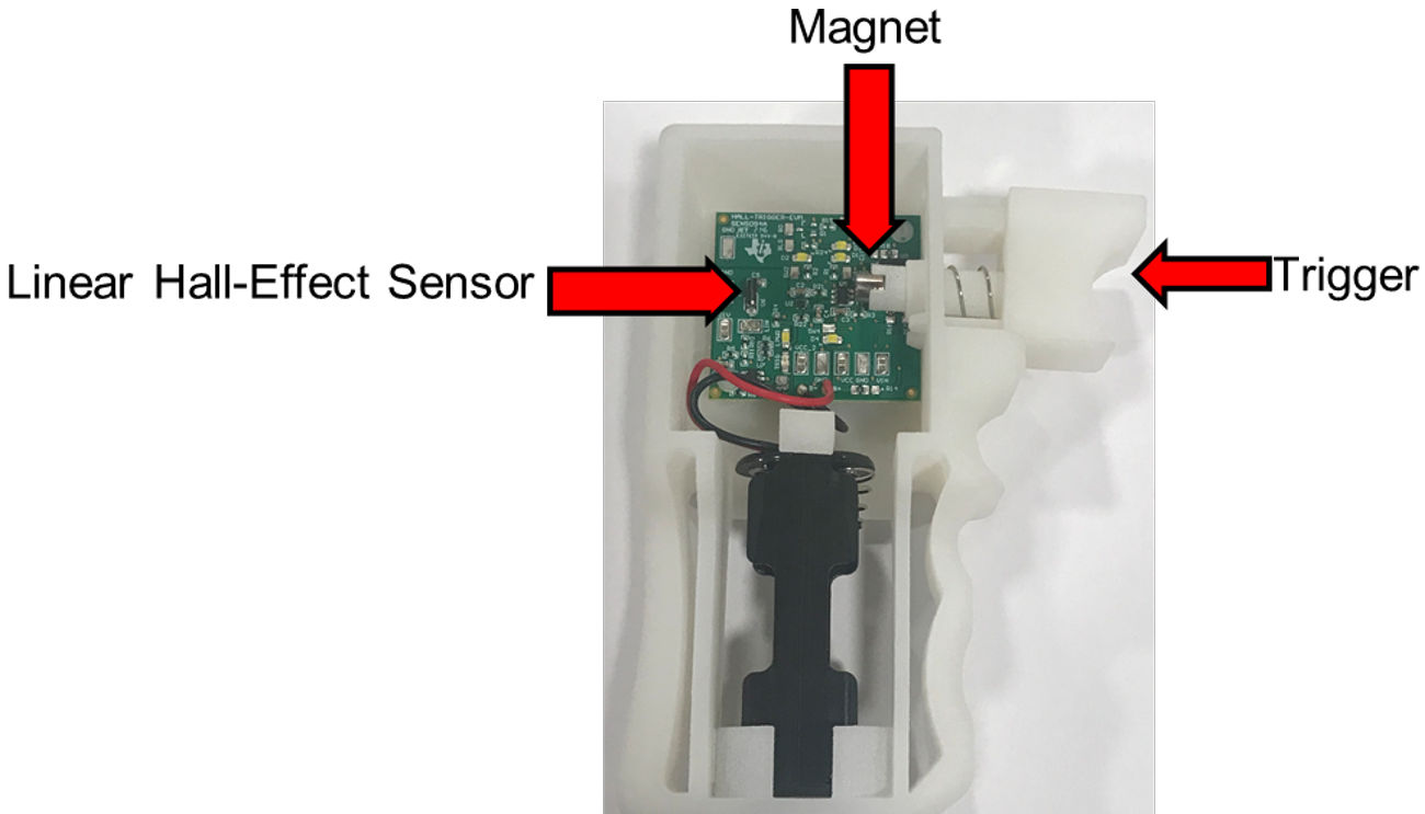
The Contactless, Hall-Effect Variable-Speed Trigger Reference Design shown in Figure 1-1 illustrates the use of a magnet and a linear Hall-effect sensor as an alternative to contact-based position sensing to determine the position of a moving component. In this reference design, a magnet placed on the moving trigger travels along with it. Pressing the trigger to the left causes the magnet and trigger to move to the left. The linear Hall-effect sensor detects the resulting magnetic flux density from the moving magnet and updates its output to reflect the position change of the trigger.
Since the relationship between magnetic flux density varies predictably based on the distance, it becomes possible to back-calculate the magnet-to-sensor distance (and therefore the moving component displacement) using the sensed magnetic flux density value. The mapping of the Hall-effect sensor’s magnetic flux density reading to distance depends on several parameters, however: the specifications of the magnet, the magnet-to-sensor orientation, the device package, and the distance from the magnet to the sensor. This article explores how to select these parameters when designing a contactless Hall-based linear position sensing system.
 Figure 1-1 TI’s contactless, hall-effect
variable-speed trigger reference design.