SLYT836 March 2023 IWR6443 , IWR6843 , IWR6843AOP
7 Beamsteering, in the direction that you want to sense
Capturing scene data with a radar sensor normally entails a course scan every frame period across the full field of view provided by the antenna beamwidths. This course scan captures reflections from objects both relevant and irrelevant, from which you need to extract and formulate particular objects, or in this case patients who need their vital signs measured. After identifying the location of the patient, it is possible to focus the beam using transmit beamforming, as mentioned previously.
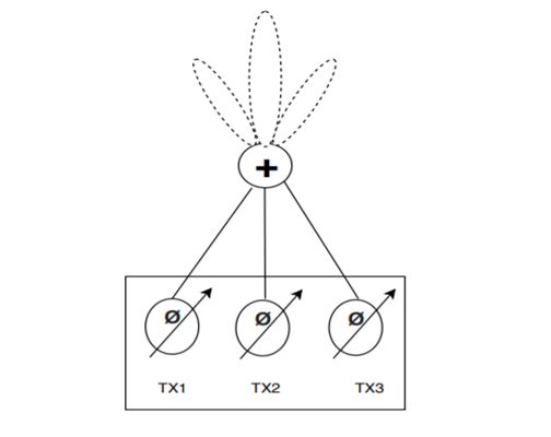
If the patient is not at boresight, then beamsteering can be activated. This functionality is enabled by 6-bit configurable phase shifters with a step size of 5.625° on each transmitter, with 64 settings available to cover the 0- to 360-° phase shift. The phase shifters are located before the respective power amplifiers and programmed individually for each transmit channel based on where to focus the main beam, see Figure 7-1. The phase shifters are typically analog structures based on a vector modulator, which uses a digital-to-analog converter to create a phase shift on the signal before being amplified.
 Figure 7-1 Phase shifters included in the
transmit stage.
Figure 7-1 Phase shifters included in the
transmit stage.You can program the phase shifters in real time for cases where there are multiple subjects at different azimuthal angles to the radar sensor – either frame to frame (typically 100 to 200 ms), or less when using subframes. For example, the beam can sweep from –60° to +60° on a subframe basis in steps of 20°, with a full scene scan lasting less than 200 ms, as shown in Figure 7-2. This facilitates the sensing of vital signs from multiple subjects across a room from wall to wall, with the subjects located at different angles and illuminated sequentially by the transmit beams.
Figure 7-2 Changing a beamsteered angle every subframe by 20°.