SLYU058D May 2021 – February 2024 TMAG5173-Q1 , TMAG5273
1 Overview
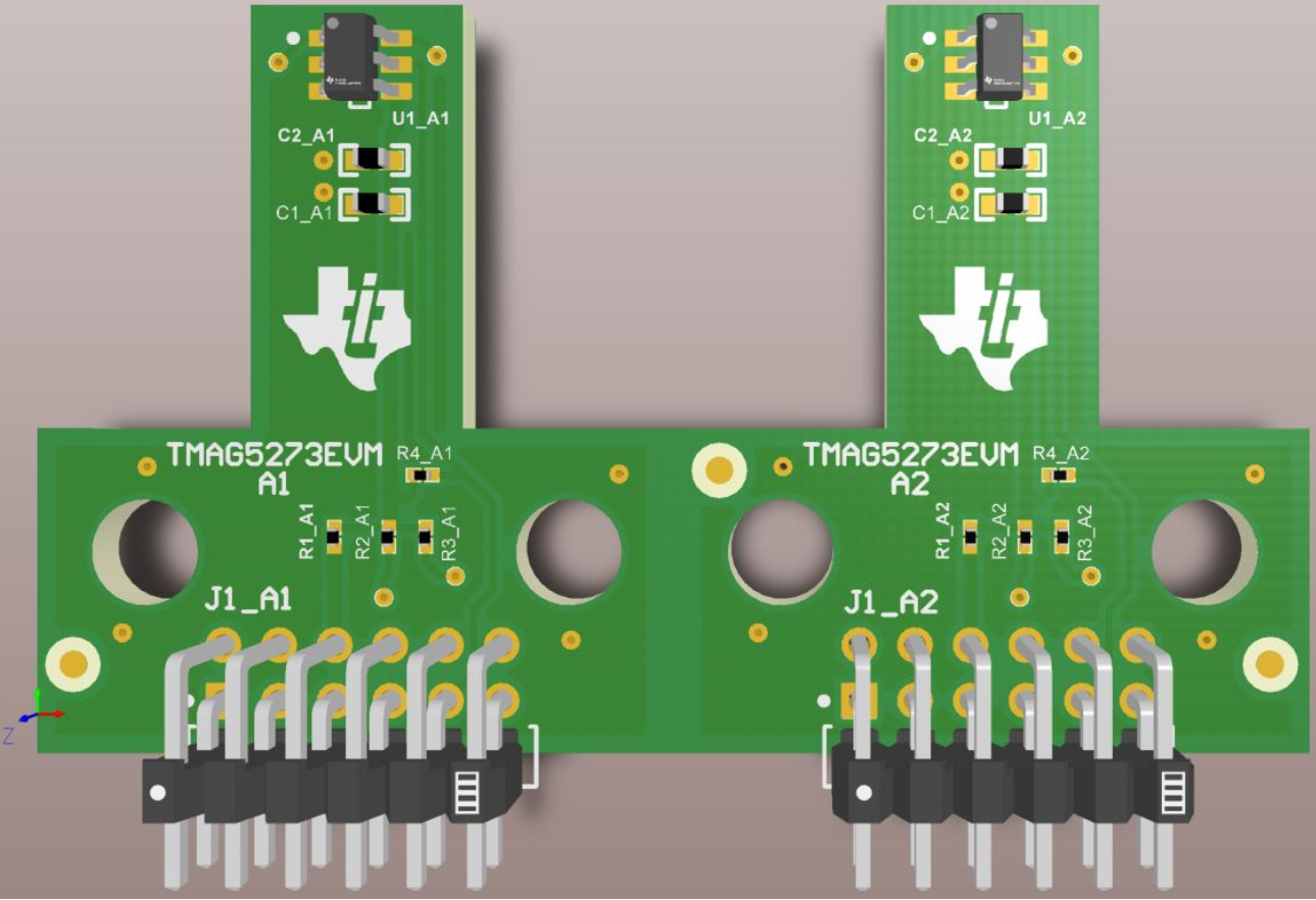
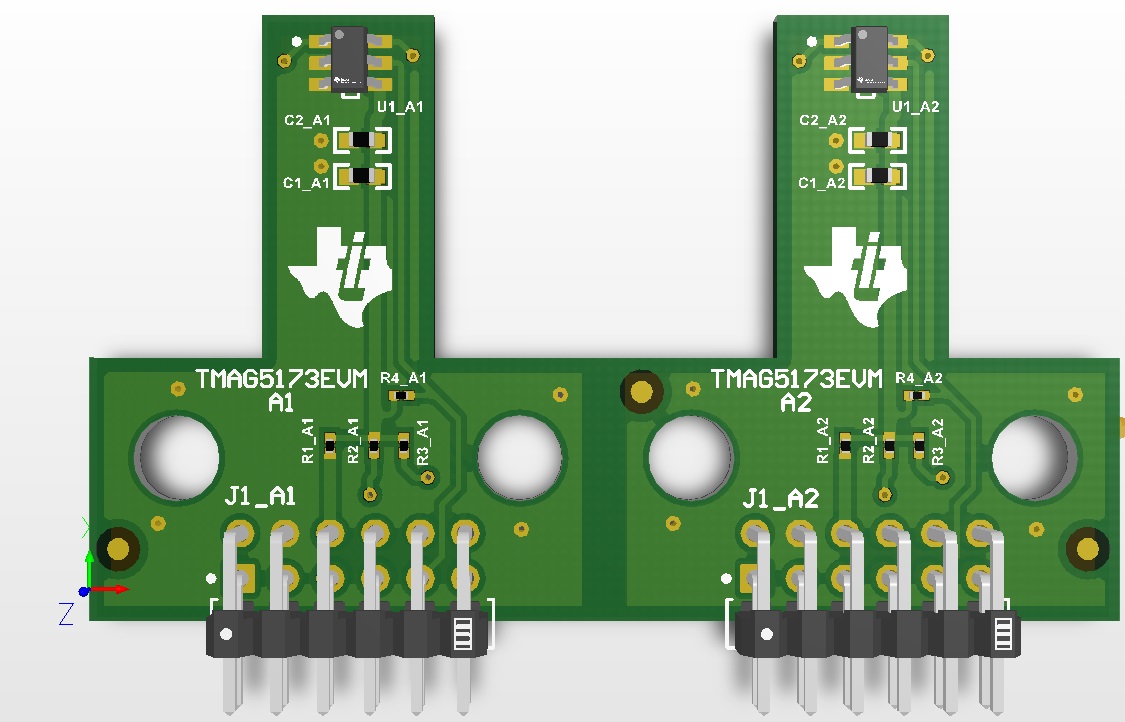
The TMAG5x73 devices are 3-axis (3D) linear Hall-effect sensors. These devices integrate three independent Hall sensors in X, Y, and Z axes. A precision analog signal-chain along with integrated 12-bit ADC digitizes the measured analog magnetic field values. The devices can be configured further to select one of two magnetic field ranges that fits the magnet strength and component placements during system calibration. Figure 1-1 shows the TMAG5273 EVM and Figure 1-2 shows the TMAG5173 EVM.
 Figure 1-1 TMAG5273 Evaluation
Module
 Figure 1-2 TMAG5173 Evaluation
Module
Figure 1-2 TMAG5173 Evaluation
ModuleThe primary difference between the TMAG5273EVM and TMAG5173EVM PCBs is that only the TMAG5273EVM has the TMAG5273 while the TMAG5173 EVM only has the automotive qualified TMAG5173 device. In addition, the PCB silkscreen on these EVMs have been updated to reference what device is on the board. One other difference between the EVMs is that the TMAG5273EVM comes with the Rotate and Push 3D print module while the TMAG5173EVM comes with the joystick 3D print module. Table 1-1 provides the summary of the sensitivity range options available for the A1 and A2 variants of the TMAG5x73 device. Each device variant supports two different range options that can be selected from in software, where each device variant has a different set of two range options that are supported. Specifically, the A1 variant of the TMAG5x73 supports either a 40-mT or 80-mT range while the A2 variant supports either a 133-mT or 266-mT range. The appropriate range is chosen so that the range is larger than the desired maximum magnetic flux density to sense. If both range options in a device can meet this requirement, selecting the smaller range setting provides the best accuracy. For example, if the maximum-sensed maximum flux density in a system is 65 mT and the A1 variant of the device is used, select the 80-mT range of the A1 device because the 40-mT range is not able to sense the maximum magnetic flux density seen in the system. The user can select both the 133-mT and 266-mT range options if the A2 device is used in this example instead, but selecting the 133-mT option provides the most accurate measurements.
| PRODUCT | SENSITIVITY RANGE OPTIONS |
|---|---|
| TMAG5x73A1 | ±40 mT, ±80 mT |
| TMAG5x73A2 | ±133 mT, ±266 mT |