SNAA366 October 2022 LMX1204
2.2 LMX1204 Multiplier Stage
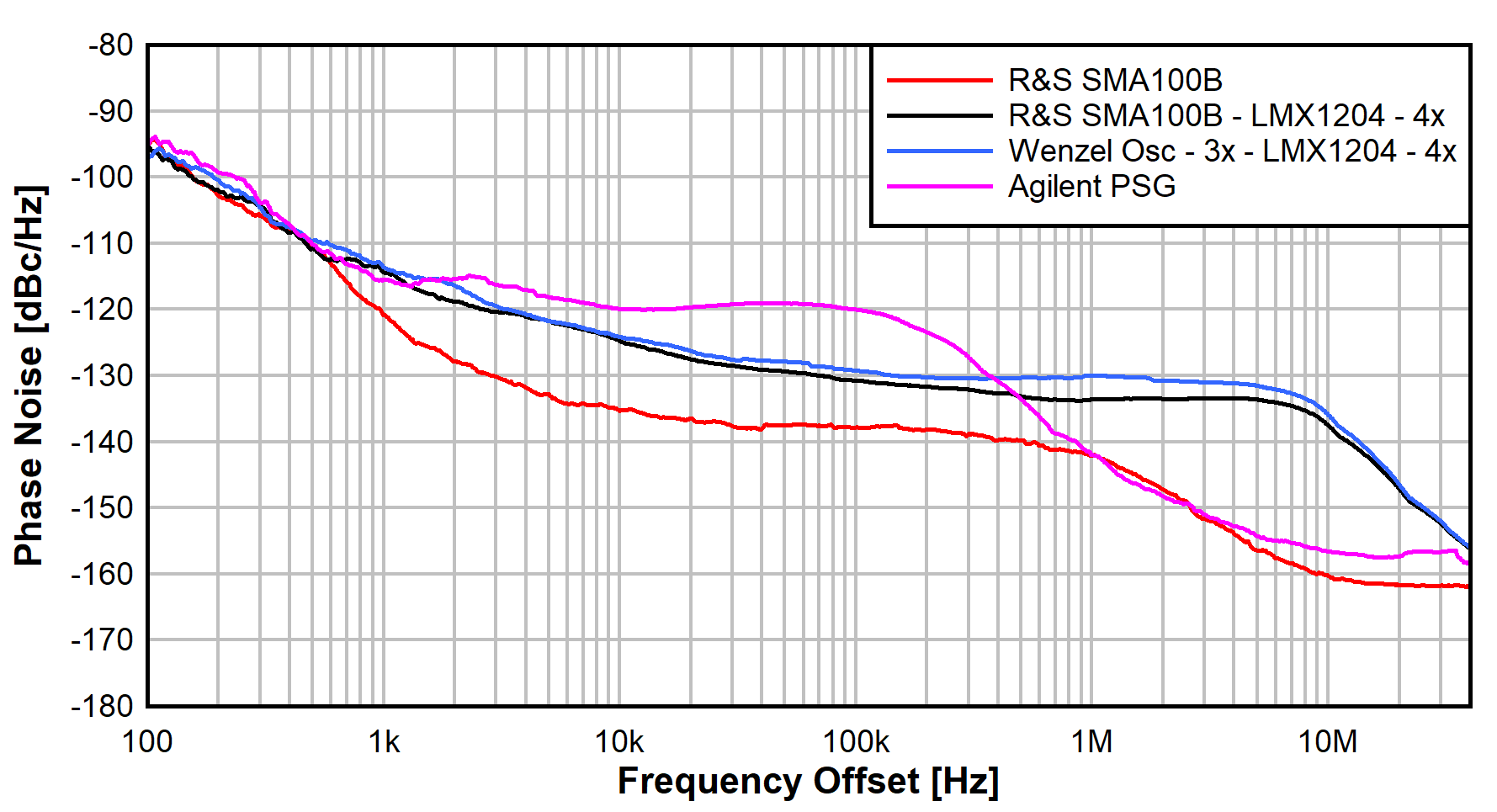
The LMX1204 device multiplies the 1474.56 MHz by 4 × to achieve the final output sampling frequency of 5898.24 MHz. Figure 2-4 shows the performance of the sample clock phase noise compared to the test equipment sources.
 Figure 2-4 Phase-Noise Comparison of
5898.24-MHz Signal
Figure 2-4 Phase-Noise Comparison of
5898.24-MHz SignalThe multiplier circuitry does introduce some phase-noise degradation, particularly evident at the higher frequency offsets beginning at around 1-MHz offset. The performance is still good and still surpasses the Agilent PSG for offsets below the 300-kHz offset. With the multiplier (and the phase-noise contribution of the multiplier) the absolute performance of the source becomes diminished; the performance using the LMX1204 multiplier with the SMA100B as the source versus the pre-multiplier as the source is nearly the same. Table 2-3 reports the integrated jitter performance.
| Frequency | Source | RMS Jitter |
|---|---|---|
| 5898.24 MHz | R&S SMA100B | 5.4 fs |
| R&S SMA100B - LMX1204 - 4x | 26.4 fs | |
| Wenzel Osc - 3x - LMX1204 - 4x | 33.6 fs | |
| Agilent PSG | 19.4 fs |