SNLA344C March 2022 – October 2023 DP83826E , DP83826I
3.1.1 Strapping Options
The section describing Hardware Bootstraps Configuration in the DP83826 Deterministic, Low-Latency, Low-Power, 10/100 Mbps, Industrial Ethernet PHY data sheet describes how the device can be configured without using the Serial Management Interface (SMI). This section of the data sheet presents configuration options in each mode: ENHANCED and BASIC. If SMI is not used to program the PHY, the DP83826 must be hardware set up in Enhanced mode to enable EtherCAT functionality.
When setting up the PHY to work in an EtherCAT® system, it is important that the PHY has an LED which is set up to show 100 Mbit full duplex and the signal polarity is active low or configurable for some ESCs.
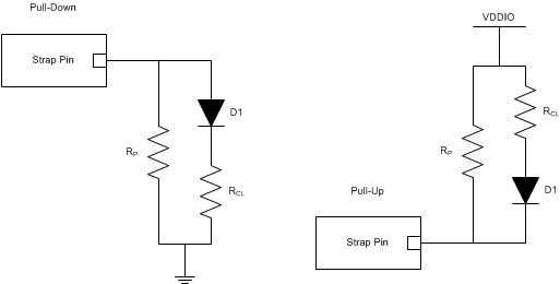
To define the LED polarity, the following circuit can be used to make either active-high or -low polarity configuration. The PHY has an internal circuit which measures the polarity that is needed and automatically configures depending on the input signal. The figure below shows the recommended networks for an active high pulldown strap circuit and an active low pull-up circuit. RP is used to define the strap network, while RCL is a current limiting resistor to protect the LED component.

Figure 3-2 Example Strap Connections
In some cases, pending the strap settings this automatic LED feature has been disabled, see section 9.4.1, Hardware Bootstrap Configuration, in data sheet for more details.
Table 3-1 can be used to determine resistor values for bootstrapping the PHY.
| Mode | Suggested Resistors | |
|---|---|---|
| RHI (kΩ) | RLO (kΩ) | |
| Internal 10-kΩ Pulldown (PD) Pins | ||
| 0-DEFAULT | OPEN | OPEN |
| 1 | 2.49 | OPEN |
| Internal 10-kΩ Pullup (PU) Pins | ||
| 0 | OPEN | 1.5 |
| 1-DEFAULT | OPEN | OPEN |
 Figure 3-3 Enhanced Bootstrap Flowchart
The information in this table shows that fast link down must be enabled in a special way. Only enable Fast link Down using RX Error Count as a detection feature. When setting up the DP83826 device to work in an EtherCAT system using Enhanced mode, use the configuration shown in Table 3-2.
| Strap Number | Pin (Pin Name) | Enhanced Mode Functionality | Default | Strap Setting |
|---|---|---|---|
| Strap 0 | pin 16 (RX_D0) |
Auto negotiation configuration Force 100Mbps communication if auto-negotiation is disabled |
0 | 0 (Enable auto-negotiation) |
| Strap 1 | pin 31 (CLKOUT/LED1) |
Odd Nibble Detection configuration When enabled, if PHY sees an uncompleted nibble of data on line, will corrupt the data and yield an RX Error. MII will also be selected as the MAC interface. |
1 | 0 (Disable Odd-Nibble Detection) |
| Strap 2 | pin 30 (LED0) | PHY_ADD0 | 0 | Define address with pull up |
| Strap 3 | pin 29 (CRS/LED3) | PHY_ADD1 | 0 | Define address with pull up |
| Strap 4 | pin 28 (COL/LED2) | PHY_ADD2 | 0 | Define address with pull up |
| Strap 5 | pin 22 (TX_CLK) | RMII mode configuration (master/slave) | 0 | 0 (master mode) This strap is a don't care due to Strap 1 forcing PHY to MII mode |
| Strap 6 | pin 20 (RX_ER) |
Functionality on Pin 31 (CLKOUT or LED1) This pin is latched at POR only and will not relatch at HW reset. |
0 | 1 (LED1) |
| Strap 7 | pin 13 (RX_D3) |
Odd Nibble Disable mode: Enable Fast Link Drop functionality for RX error mechanism Odd Nibble Enable mode: Enable Fast Link Drop functionality for all mechanisms except MLT-3 RMII Mode: Repeater configurable |
0 | 1 (FLD enabled for RX error) |
| Strap 8 | pin 14 (RX_D2) |
Odd Nibble Disable Mode: If signal detect is enabled (pin 13), configure for signal energy detect mechanism Odd Nibble Enable Mode: Choose MAC interface |
0 | 1 (Signal Energy Detect disabled) |
| Strap 9 | pin 15 (RX_D1) | Auto MDIX Configurability | 0 | 0 (Auto-MDIX enabled) |
| Strap 10 | pin 18 (RX_DV) | Auto-MDIX Disable mode: Set MDI or MDIX | 0 |
0 (MDIX) Not needed due to auto MDIX enabled |
| Pin 1 (ModeSelect) | Mode Select: Enhanced or Basic | 1 | 1 (Enhanced mode) |