SNVAA22 June 2021 LP8867-Q1 , TMP61-Q1
3 LP886x-Q1 TSET Implementation
The LP886x-Q1 has an optional feature to decrease automatically LED current when LED overheating is detected with an external PTC sensor. An example of the behavior is shown in Figure 3-1. When the PTC temperature reaches T1, the LP886x-Q1 starts to decrease the LED current. When the LED current has reduced to 17.5% of the nominal value, current turns off until temperature returns to the operation range.
When external NTC (PTC) is connected, the pin current decreases LED output current. Temperature T1 and de-rate slope are defined by external resistors as explained below.
Parallel resistance of the PTC sensor and resistor R4 is calculated by formula:
- is the bias voltage of the resistor group. It is recommended to connect with chip's internal LDO output (pin 2)
| R1 | 5kΩ |
| RT | 6.5kΩ |
| R2 | 10kΩ |
| R3 | PTC |
| R4 | DNP |
| R5 | 1kΩ |
| RISET | 2.4kΩ |
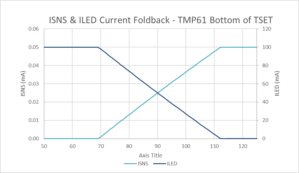
The output current thermal foldback profile in Figure 3-3 is achieved:
 Figure 3-3 Current Foldback Profile with
TMP61