SNVAA72 april 2023
Other Parts Discussed in Post: TPSF12C3-Q1, TPSF12C1-Q1
Automotive on-board chargers and server power supplies are highly constrained system environments where power density is a primary metric. It’s important to reduce the volume of the electromagnetic interference (EMI) filter components so that the solution can fit into demanding form factors.
Common-mode (CM) filters for these and other high-density applications often limit the total Y-capacitance – related to touch-current safety requirements – and thus require large-sized CM chokes to achieve a target corner frequency or filter attenuation characteristic. The result is a compromised passive filter design with bulky, heavy and expensive CM chokes that dominate the overall filter size.
With advances in passive components lagging behind high-speed power semiconductor devices as well as circuit topologies, the volume of the passive filter is one of the limiting factors for increasing power density. Practical filter implementations can occupy as much as 30% of the total volume of a power solution, as shown in Figure 1.
 Figure 1 A conventional single-phase
passive EMI filter in a 3.3-kW totem-pole power factor correction reference
design
Figure 1 A conventional single-phase
passive EMI filter in a 3.3-kW totem-pole power factor correction reference
designReduce system size, weight and cost
|
Learn more about our power-supply filter ICs. |
Active EMI filter (AEF) circuits enable more compact filter solutions for next-generation power-management systems. Space-constrained applications can use active power-supply filter integrated circuits (ICs) to reduce the size of magnetic components and the overall filter. Additional benefits of an AEF include lower component power losses for better thermal management and higher reliability, reduced coupling between components within a confined space, easier mechanical and packaging design, and lower costs.
Figure 2 and Figure 3 are schematics of single-phase and three-phase filter circuits, respectively, where an active solution replaces a traditional passive design. The single-phase TPSF12C1, TPSF12C1-Q1 and three-phase TPSF12C3, TPSF12C3-Q1 AEF ICs, positioned between the CM chokes, provide a lower-impedance shunt path for CM currents. As illustrated, the active solution has CM chokes LCM1 and LCM2 with much lower inductance relative to the same components in the passive filter.
 and corresponding AEF circuit with lower CM choke inductances
(bottom)") Figure 2 Single-phase passive EMI
filter (top) and corresponding AEF circuit with lower CM choke inductances
(bottom)
Figure 2 Single-phase passive EMI
filter (top) and corresponding AEF circuit with lower CM choke inductances
(bottom) and corresponding AEF circuit with lower CM choke inductances
(bottom)") Figure 3 Three-phase passive EMI filter
(top) and corresponding AEF circuit with lower CM choke inductances
(bottom)
Figure 3 Three-phase passive EMI filter
(top) and corresponding AEF circuit with lower CM choke inductances
(bottom)AEFs
With Y-rated sense and injection capacitors connected to the AC lines, the circuits aim to reduce the total filter volume yet maintain low values of the line-frequency leakage current to chassis ground. This is possible by using an active circuit that shapes the frequency response of the injection capacitor – effectively increasing its value for high frequencies. In turn, the amplified injection capacitance over the frequency range of interest for EMI mitigation will lower CM choke inductances relative to the values of a passive filter with comparable attenuation.
The circuit advantages using an AEF are:
- A simpler filter structure with a wide operating frequency range and high stability margins (calculated using the common-mode AEF quickstart calculator tool).
- A reduced CM choke size with lower volume, weight and cost. This also enables much lower copper losses and better high-frequency attenuation performance from reduced choke self-parasitics.
- No additional magnetic components – the AEF circuit only uses Y-rated sense and injection capacitors, with no impact to peak touch current during a fault condition.
- Enhanced safety using a low-voltage AEF IC referenced to chassis ground.
- A stand-alone IC implementation that offers flexibility in terms of placement near the filter components.
- Immunity to line voltage surges to help meet International Electrotechnical Commission 61000-4-5.
The X-capacitor(s) placed between the two CM chokes in Figure 4 and Figure 5 provide a low-impedance path between the power lines from a CM standpoint, typically up to low-megahertz frequencies. This allows current injection onto one power line, usually neutral, using only one injection capacitor. If the three-phase filter is a three-wire system without a neutral, the SENSE4 pin of the TPSF12C3-Q1 ties to ground and the injection capacitor couples through a starpoint connection of the X-capacitors.
Practical AEF implementation
Figure 4 shows a practical AEF implementation suitable for the converter in Figure 1. Using the TPSF12C1-Q1 single-phase AEF IC achieves CM noise attenuation.
 Figure 4 Single-phase filter evaluation
board with the AEF rated at 10 A
Figure 4 Single-phase filter evaluation
board with the AEF rated at 10 AFigure 5 shows EMI results with the AEF disabled and enabled.
 Figure 5 EN 55032 Class B EMI results
with the AEF disabled and enabled
Figure 5 EN 55032 Class B EMI results
with the AEF disabled and enabledAs evident in Figure 5, an AEF provides up to 30 dB of CM noise attenuation in the low-frequency range (100 kHz to 3 MHz), which enables a filter using two 2-mH nanocrystalline chokes to achieve CM attenuation performance equivalent to a passive filter design with two 12-mH chokes. To make a fair comparison, these chokes come from the same component family (made by Würth Elektronik) with a similar core material. Table 1 captures the applicable CM-choke parameters for the passive and active designs, and Figure 6 highlights the volume, footprint, weight and cost savings.
| Filter design | CM choke part number | Qty |
LCM1, LCM2 (mH) |
RDCR (mΩ) |
Size (L × W × H, mm) |
Total mass (g) |
Total power loss (W) at 10 A, 25°C |
|---|---|---|---|---|---|---|---|
| Passive | 7448051012 | 2 | 12 | 15 | 23 × 34 × 33 | 72 | 6.0 |
| Active | 7448031002 | 2 | 2 | 6 | 17 × 23 × 25 | 20 | 2.4 |
; choke size
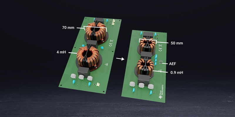
comparison (b)") Figure 6 Footprint, volume, weight and
cost reductions enabled by an AEF (a);
Figure 6 Footprint, volume, weight and
cost reductions enabled by an AEF (a);choke size comparison (b)
The AEF in this example achieves a 60% total copper loss reduction at 10 A (neglecting the winding resistance increase from the temperature rise), which implies lower component operating temperatures and improved reliability.
Conclusion
It’s challenging to achieve a compact and efficient design for the EMI filter stage in high-density switching regulators, particularly for automotive and industrial applications where solution size and cost are such priorities. Practical results from an active filter solution to suppress the measured CM noise signature indicate a significant volumetric reduction of the CM choke components when benchmarked against an equivalent passive-only filter design.
Additional resources:
- Watch a video on active EMI filtering: Single- and three-phase active EMI filter ICs mitigate common-mode EMI, save space and reduce cost.
- Review these white papers:
- For more details about the example in Figure 1, showing a conventional filter design, see the High efficiency GaN CCM totem pole bridgeless Power Factor Correction (PFC) reference design.