SPRACR5A february 2020 – may 2023 AWR2243
2.1.1 Image Load Sequence
In functional mode, the bootloading of an image from the SDF is the first bootmode attempted by the bootloader. This involves the following steps:
- Pinmux the QSPI pins of AWR2243 device
- QSPI[0]: Ball R11
- QSPI[1]: Ball P9
- QSPI[2]: Ball R12
- QSPI[3]: Ball P10
- QSPI_CLK: Ball R10
- QSPI_CS_N: Ball P8
- QSPI is setup to operate at (System clock/5) = (200/5) = 40 MHz
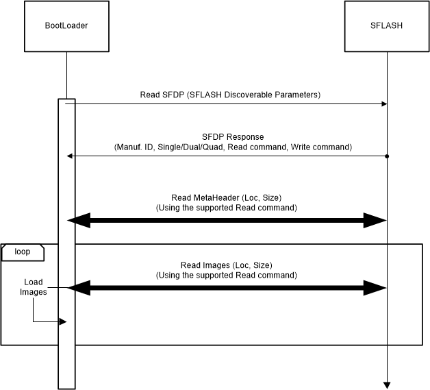
- The SFLASH Discoverable Parameters (SFDP) command is issued to retrieve the JEDEC compliant response that includes information regarding the SFLASH capabilities and command set. On successful reception of the SFDP response, the information is used to communicate with the SDF and further interpret the contents and load the images.
 Figure 2-2 Image Load Sequence
Key Points:
- The ROM bootloader performs the read from the SDF based on the highest capability mode (Quad/Dual/Single) as published by the SDF in response to the SFDP command.
- For SDF variants that support Quad mode, the Quad mode commands will be issued and in case the Quad Enable (QE) bit is not set, the communication will fail. In such cases, the load flow expects that the “Quad Enable (QE)” bit in the SDF is already set.