SPRACR5A february 2020 – may 2023 AWR2243
3.4 Flashing Sequence
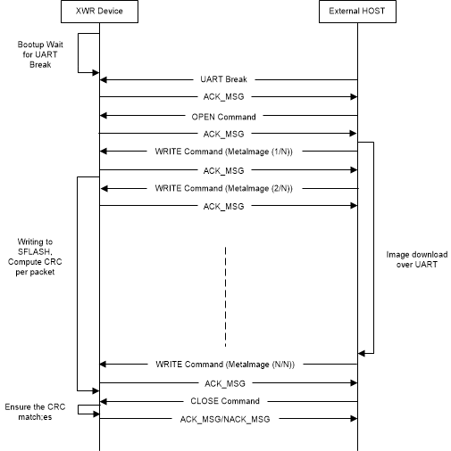
Figure 3-2 shows the flash programming sequence. The initial handshake starts with a UART break issued by the external host. This break is followed by the command sequence in Figure 3-2. The bootloader uses a command-response protocol. So the host should wait after sending each command until an ACK response is received from the device. Note that the GET STATUS command is unique in that it returns only the STATUS RESPONSE message without sending an ACK response.
 Figure 3-2 Flashing Sequence
Key Points:
- The host processor needs to split the each file/image into smaller chunks and send each chunk in a WRITE TO FLASH command. The LENGTH field of the command should be set to the total payload size (which includes the image data chunk and 1 byte for the 0x24 opcode) + 2. The max chunk size is243 - 3 = 240 bytes.
- The byte order for the words in the UART commands is big-endian (i.e. transmit most-significant byte first). The BSS/MSS/Config images should be transmitted as bytes in the order they are in the binary files.
- The ERASE command is not required but can be used to make sure the entire SDFLASH is cleared before the new images are written.
- The GET STATUS command is not required but can be used to check status of device.
- The GET VERSION command not required but can be used by the host processor to allow it to operate differently depending on the device silicon version.