SPRADD2 august 2023 AM62A3 , AM62A3-Q1 , AM62A7 , AM62A7-Q1
- 1
- Abstract
- Trademarks
- 1 Introduction
- 2 AM62A Processor
- 3 System Block Diagram
- 4 Driver and Occupancy Mirror System Data Flow
- 5 Deep Learning Acceleration
- 6 Functional Safety in DMS/OMS Applications Using AM62A
- 7 Functional Safety Targets and Assumptions of Use
- 8 Functional Safety in DMS/OMS Data Flow
- 9 LED Driver Illumination Use Case
- 10Summary
- 11References
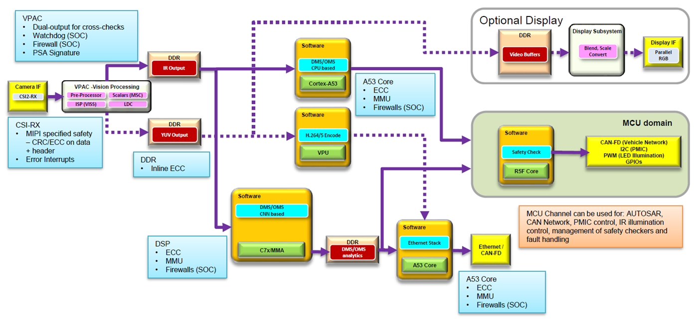
8 Functional Safety in DMS/OMS Data Flow
Take the DMS/OMS data flow mentioned in Section 4 and break it down to see how IP specific functional safety diagnostics can be leveraged. Note that the safety mechanisms can be a combination of hardware as well as software diagnostic mechanisms that need to implemented by system integrator.
 Figure 8-1 DMS/OMS Data Flow With
Hardware Provided Safety Mechanisms
Figure 8-1 DMS/OMS Data Flow With
Hardware Provided Safety MechanismsNote: The analysis below assumes safety criticality in each step
of the data flow/application. Other concepts which assume QM processing in main
domain and safety function including safety monitoring in the MCU domain may be
employed.
Note: Key IP involved in the data flow have been listed. Several
other IP performing functions such as DMA, Inter-processor communication, boot haven
not been listed. Failure modes and safety mechanisms shown here are a sample set.
For complete recommendation of safety mechanism combinations to meet desired safety
integrity levels, please refer the AM62Ax Functional Safety Manual.
Table 8-1 Data Flow Considerations in
DMS/OMS Data Flow
| Step in Data Flow | IP Involved and Failure Modes | Safety Mechanisms |
|---|---|---|
| 1. Camera capture of RGB-IR data source | CSI-RX No image data transmitted or image corruption Hang during image data transmission |
Hardware mechanisms – MIPI specified packet protocol
checks, error interrupts, ECC protection of RAM data, watchdog Software mechanisms – Software processing of pixels within a frame and frame to frame |
| 2. Transfer of camera captured data to DRAM for VPAC to read and process as well as to store processed image data | DDR Corruption of image data due to fault in DDR controller or interference due to lower ASIL function |
Hardware mechanisms – DDR controller provided
multi-phase ECC, device firewalls for isolation Software mechanisms – Information redundancy techniques applied to image data |
| 3. Image processing of RGB+IR data and split of data into RGB and IR streams for further analysis | VPAC Corruption of image data Hang resulting in incorrect program flow |
Hardware mechanisms – HWA (HTS) timers, internal
watchdog timers, VPAC provided PSA signature computation, ECC/parity
on critical memories Software mechanisms – Software processing of pixels within a frame and frame to frame, Golden Frame Testing |
| 4. CNN based calculations for analytics of image data, Deep Learning Accelerator | C7x and MMA Corruption of image data Incorrect program execution causing algorithm to take incorrect decisions |
Hardware mechanisms – C7x provided MMU, ECC on
memories, device firewalls for isolation, dedicated watchdog Software mechanisms – Program flow monitoring or reciprocal comparison using another software implementation of DMS algorithm running on A53 core. Note – Software mechanisms such as program flow monitoring and reciprocal comparison by software are recommended in ISO 26262:2018-5 |
| 5. CPU based DMS algorithms running using classical vision
techniques (Optionally – can be used for cross-checking the C7x core execution) |
A53 core Incorrect program execution causing algorithm to take incorrect decision |
Hardware mechanisms – MMU, ECC on memories, device
firewalls for isolation, dedicated watchdog Software mechanisms – Program flow monitoring or reciprocal comparison by software, ARM provided STL mechanisms. Note – Software mechanisms such as program flow monitoring and reciprocal comparison by software are recommended in ISO 26262:2018-5. |
| 6. AUTOSAR and CAN communication with external ECU, PMIC control, IR illumination control | MCU channel – MCU R5 core, MCU dedicated CAN Failure in communication with external ECU due to unresponsive core Message corruption Lower ASIL function from main domain causing interference with MCU domain function Incorrect program execution |
Hardware mechanisms – ECC on MCU R5, CAN memories,
LBIST on MCU R5 core, CAN protocol specific error detection, SOC
firewalls for isolation, isolation mechanisms between Main and MCU
domain. Software mechanisms – CRC in CAN message, program sequence monitoring on core, reciprocal comparison using another core on device |