SPRUIR8B april 2020 – july 2023
- 1
- CLB Tool
- Trademarks
- 1Introduction
- 2Getting Started
- 3Using the CLB Tool
-
4Examples
- 4.1
Foundational Examples
- 4.1.1 CLB Empty Project
- 4.1.2 Example 3 – PWM Generation
- 4.1.3 Example 7 – State Machine
- 4.1.4 Example 13 – PUSH-PULL Interface
- 4.1.5 Example 14 – Multi-Tile
- 4.1.6 Example 15 – Tile to Tile Delay
- 4.1.7 Example 16 - Glue Logic
- 4.1.8 Exampe 18 - AOC
- 4.1.9 Example 19 - AOC Release Control
- 4.1.10 Example 20 - CLB XBARs
- 4.2
Getting Started Examples
- 4.2.1 Example 1 – Combinatorial Logic
- 4.2.2 Example 2 – GPIO Input Filter
- 4.2.3 Example 4 – PWM Protection
- 4.2.4 Example 5 – Event Window
- 4.2.5 Example 6 – Signal Generation and Check
- 4.2.6 Example 8 – External AND Gate
- 4.2.7 Example 9 – Timer
- 4.2.8 Example 10 – Timer With Two States
- 4.2.9 Example 11 – Interrupt Tag
- 4.2.10 Example 12 – Output Intersect
- 4.2.11 Example 17 – One-Shot PWM Generation
- 4.2.12 Example 21 - Clock Prescaler and NMI
- 4.2.13 Example 22 - Serializer
- 4.2.14 Example 23 - LFSR
- 4.2.15 Example 24 - Lock Output Mask
- 4.2.16 Example 25 - Input Pipeline Mode
- 4.2.17 Example 26 - Clocking Pipeline Mode
- 4.3 Expert Examples
- 4.1
Foundational Examples
- 5Enabling CLB Tool in Existing DriverLib Projects
- 6Frequently Asked Questions (FAQs)
- 7Revision History
1.2 Overview of the CLB Configuration Process
The CLB tool is based on the SysConfig tool in CCS. The generated C header and source files, combined with the C2000Ware SDK, can configure the CLB. To conduct a simulation of the design a number of third party tools need to be installed, including a compiler and a wave viewer. For more information on the CLB simulator, see Section 3.5.
The CLB tool generates a “.dot” file which shows sub-module inter-connections in diagram form and can help verify the design. This file is created in HTML and SVG formats using CCS post-build steps. These steps use node.js and JavaScript libraries which are in the provided examples. The tool also generates a “clb_sim.cpp” file. The CPP file, along with other CLB simulation models, is compiled using a GCC compiler. The output of the compilation is an “.exe” file, which must be executed on the local machine in order to generate a “.vcd” file. This “.vcd” file can be used to conduct a timing analysis using an external graph viewer. All these steps are done by the "clb_simulation" file which is generated by the tool. This file will be either a batch (.bat) or shell (.sh) file depending on the operating system used (the images used in this user's guide are based on the Windows operating system). This file must be executed to generate the appropriate ".vcd" file.
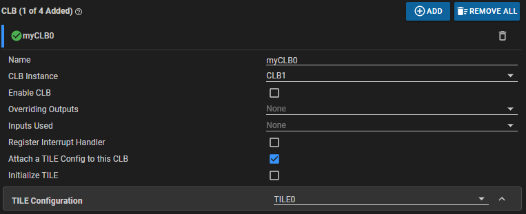
The CLB configuration is encoded in the generated C header file “clb_config.h”. The “clb_config.c” file generated by the CLB tool uses the generated header file to load the configuration into the CLB module’s registers. The CLB module within SysConfig must have the appropriate Tile Design attached for the configuration to actually take place, as shown in Figure 1-1. The independence between Tile Designs and the CLB module in SysConfig allows any number of tile configurations to be created while having a limited number of CLB instances on a device. These Tile Designs are selectively loaded into the CLB.
 Figure 1-1 Attaching Tile Design to CLB
Instance
Figure 1-1 Attaching Tile Design to CLB
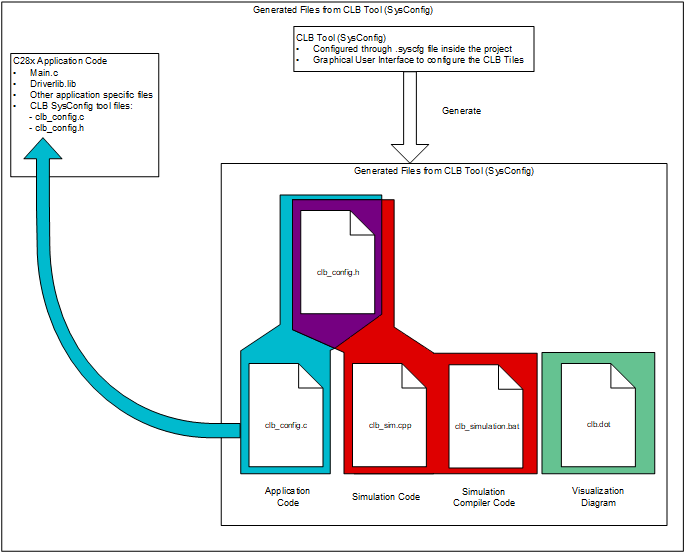
InstanceIt is important to note that in the application code for the C28x device, the functions in the “clb_config.c” file must be called during the device initialization steps. Figure 1-2 shows the output of the CLB tool and the post-build steps.
 Figure 1-2 CLB Tool Project
Structure
Figure 1-2 CLB Tool Project
StructureIn a typical scenario, the user begins by specifying the CLB logic functionality. This may be in the form of a logic circuit diagram, timing information, written description, VHDL code, or some other form. Having installed the requisite tools, the first step will be to connect the tile sub-modules to implement the desired logic.
The specification may include a set of timing diagrams in which case the user may choose to conduct a simulation of the CLB configuration to ensure behavior is as expected. This step includes defining a set of input test stimuli and building a simulation project to generate simulation waveforms which can be opened in a graph viewer. If the results are not as expected, the user can modify the CLB tool settings and repeat the simulation.
Once the simulation produces the correct waveform, the user can download the design into the device using CCS to run or debug the code.
In a CCS project with SysConfig enabled for a C28x device, the steps to create the HTML and SVG block diagram of the Tile Designs is done as part of the post-build steps. When the user builds the CCS project, the user application code and the generated “clb_config.h” and “clb_config.c” are compiled using the C28x compilers and a “.out” file is generated.
The "clb_simulation" file compiles the generated simulation files, “clb_sim.cpp” and “clb_config.h”, and the CLB simulation modes using a GCC compiler. The output of this step is a “.exe” file (“simulation_output.exe”) which is automatically run to generate the “CLB.vcd” file. This file can be viewed using an external graph viewer.
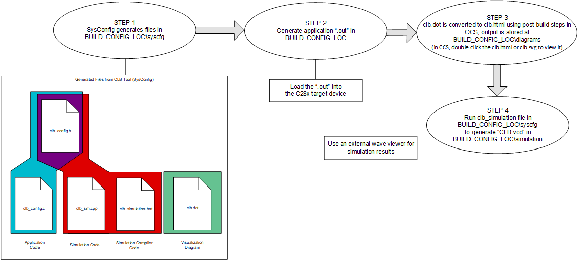
 Figure 1-3 CLB Tool Build Process
In CLB Tool Build Process the BUILD_CONFIG_LOC directory is the directory used as the build configuration output for the project (this can be "Debug", "CPU1_RAM", and so forth), and shares the name of the active build configuration.