SPRUIY1C November   2020  – April 2024


  1.   1
  2.   Description
  3.   Features
  4.   4
  5. 1Evaluation Module Overview
    1. 1.1 Introduction
    2. 1.2 Preface: Read This First
      1. 1.2.1 If You Need Assistance
      2. 1.2.2 Important Usage Notes
    3. 1.3 Kit Overview
      1. 1.3.1 Kit Contents
      2. 1.3.2 Key Features
      3. 1.3.3 Component Identification
      4. 1.3.4 Daughter Cards
        1. 1.3.4.1 Connecting the AM273x EVM to the AWR2243BOOST EVM
        2. 1.3.4.2 Connecting the AM273x EVM to the DCA1000
      5. 1.3.5 Security
      6. 1.3.6 Compliance
  6. 2Hardware
    1. 2.1 Board Setup
      1. 2.1.1 Power Requirements
        1. 2.1.1.1 Power Status LEDs
      2. 2.1.2 Push Buttons
      3. 2.1.3 Switches
      4. 2.1.4 LEDs
      5. 2.1.5 Boot Mode Selection
    2. 2.2 Hardware Description
      1. 2.2.1  Functional Block Diagram
      2. 2.2.2  Memory Interface
        1. 2.2.2.1 QSPI Interface
        2. 2.2.2.2 Board ID EEPROM
      3. 2.2.3  Ethernet Interface
      4. 2.2.4  Micro USB Interfaces
        1. 2.2.4.1 FTDI USB Interface
          1. 2.2.4.1.1 FTDI EEPROM Memory Device
        2. 2.2.4.2 XDS USB Interface
        3. 2.2.4.3 PC Connection
      5. 2.2.5  I2C Interface
        1. 2.2.5.1 I2C Connections
      6. 2.2.6  UART Interface
      7. 2.2.7  CAN Interfaces
        1. 2.2.7.1 CAN-A Interface
        2. 2.2.7.2 CAN-B Interface
      8. 2.2.8  JTAG Emulation
      9. 2.2.9  SPI Interface
      10. 2.2.10 MDI Interface
      11. 2.2.11 ePWM Interface
    3. 2.3 Connectors
      1. 2.3.1 60-Pin High Density (HD) FE Connector-1 (J1)
      2. 2.3.2 60-Pin High Density (HD) FE Connector-2 (J11)
      3. 2.3.3 MIPI 60-Pin Connector (J19)
      4. 2.3.4 Debug Connector 60-Pin (J7)
      5. 2.3.5 External Clock Option (J13, J1)
    4. 2.4 Mechanical Mounting of the PCB
  7. 3Additional Information
    1. 3.1 Trademarks
    2.     3.A Rev. C Design Changes
  8. 4Revision History

PC Connection

The connectivity is provided through the micro USB connector over the onboard XDS110 (TM4C1294NCPDT) emulator. This provides the following interfaces to the PC:

  • JTAG for CCS connectivity
  • MSS logger UART. This can be used to get MSS code logs on the PC

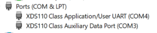
When the USB is connected to the PC, the device manager recognizes two XDS110 COM ports under Ports (COM and LPT).

TMDS273EVM, TMDS273GPEVM, TPR12REVM

XDS110 debug probe and data port are detected under Texas Instruments Debug Probes.

TMDS273EVM, TMDS273GPEVM, TPR12REVM

If the PC is unable to recognize the above COM ports, then install the EMU pack available at the following link:

https://software-dl.ti.com/ccs/esd/documents/xdsdebugprobes/emu_xds_software_package_download.html