SPRUIY1C November 2020 – April 2024
- 1
- Description
- Features
- 4
- 1Evaluation Module Overview
-
2Hardware
- 2.1 Board Setup
- 2.2 Hardware Description
- 2.3 Connectors
- 2.4 Mechanical Mounting of the PCB
- 3Additional Information
- 4Revision History
2.1.4 LEDs

Figure 2-4 AM273x EVM LEDs
Table 2-5 LED Information
| Ref | Color | Usage | Comments | Image |
|---|---|---|---|---|
| D12 | Green | 12V supply indication | This LED indicates the presence of 12V supply input. | 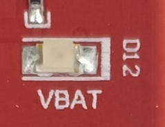 |
| D16 | Green | 5V PMIC Supply | This LED indicates the presence of 5V supply output from PMIC. | 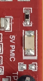 |
| D2 | Green | 5V FE Supply | This LED indicates the presence of 5V supply for FE connectors. | 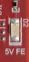 |
| D13 | Yellow | nRESET | This LED is used to indicate the state of nRESET pin. If this LED is glowing, then the device is out of reset. | 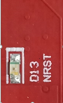 |
| DS2 | Red | NERR_OUT | Glows if there is any HW error in the AM273x device. | 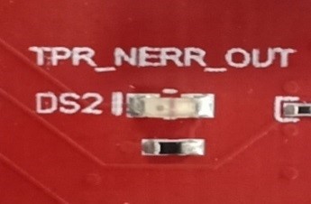 |
| D9 | Yellow | WRMRST | Open drain fail safe warm reset signal. | 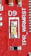 |
| D6 | Green | GPIO_2 | Glows when the GPIO_2 is logic-1. | 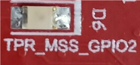 |