SSZT061 october 2022 AM2631-Q1 , AM2632-Q1 , AM2634-Q1

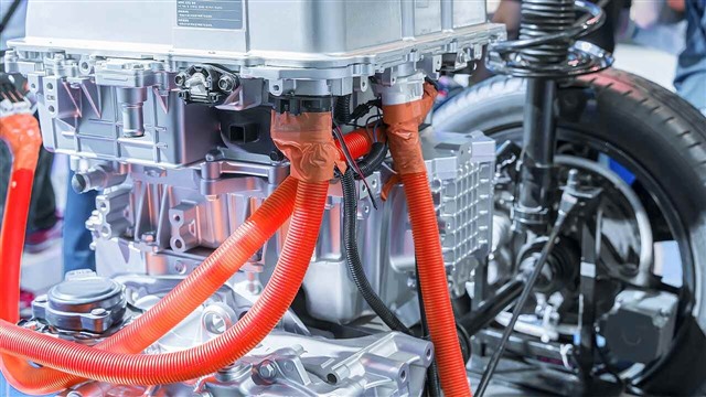
The electric vehicle (EV) traction inverter is the core of the EV. It converts DC from the high-voltage battery to multiphase (usually three-phase) AC to drive the traction motor, and also controls power regeneration from braking. EV electronics are shifting from 400-V to 800-V architectures, which promise:
- Fast charging – delivering double the power at the same current.
- Improved efficiency and power density by taking advantage of silicon carbide (SiC).
- Reduced weight through the use of thinner cables by reducing the current needed at 800 V for the same power rating.
In a traction inverter, the microcontroller (MCU) is the brains of the system, performing motor control, sampling voltage and current with analog-to-digital converters (ADCs), computing the field-oriented control (FOC) algorithm with the core, and actuating the power field-effect transistors (FETs) with pulse-width modulation (PWM) signals. For the MCU, the shift to an 800-V traction inverter creates three challenges:
- Lower latency real-time control performance demands.
- Increased functional safety requirements.
- The need to quickly respond to system faults.
In this article, I’ll discuss how devices such as the Arm®-based Sitara™ AM2634-Q1 and C2000™ MCU address these challenges.
Lower-latency Real-time Control
In order to control the torque and speed of the traction motor, the MCU uses a combination of peripherals (ADCs, PWMs) and computation cores to complete the control loop. With the move toward 800-V systems, traction inverters are also moving toward wide-bandgap semiconductors such as SiC given their greatly increased efficiency and power density at 800 V. In order to achieve the higher switching frequencies that SiC requires, such control-loop latency becomes a priority. A low-latency control loop also enables engineers to run the motor at a higher rpm, which can reduce both size and weight of the motor. To understand and reduce control-loop latency, you must understand the control-loop signal chain and its individual stages, as shown in Figure 1.
 Figure 1 The Control-loop Signal Chain
For the best real-time control performance, you must optimize the whole signal chain, including both hardware and software. The time it takes from ADC sampling (input from the motor) to writing the PWM (output to control the motor) is the fundamental measure of real-time control performance. Starting with ADC sampling, inverter systems need accurate and fast sampling – meaning a high sample rate, at least 12 bits of resolution and a low conversion time. Once the sample is available, it needs to be transferred to and read by the processor through an interconnect, with low latency from an optimized bus and memory access architecture. At the processor, the cores need to compute the next PWM step based on phase currents, speed and the position of the motor, using an FOC algorithm.
To minimize this computation time, the core needs a high clock speed and must execute the number of instructions efficiently. Additionally, the core needs to execute a range of instruction types, including floating-point, trigonometric and integer math instructions. Finally, the core writes the updated duty cycle to the PWM generator, again using a low-latency path. Applying deadband compensation on the PWM outputs will prevent a short circuit when switching the high- and low-side FETs, preferably applied at a hardware level to reduce software overhead.
TI MCUs have traction inverter control-loop latency as low as 2.5 µs, with the AM2634-Q1 demonstrating latency <4 µs. This level of control-loop latency will future-proof future designs, including SiC architectures.
Increased Functional Safety Requirements
Because traction inverters deliver power to control the motor, they are inherently a critical system for functional safety. And because 800-V systems have the potential for higher power, torque, speed or all three, traction systems demand the Automotive Safety Integrity Level (ASIL) D level of functional safety. A critical piece of the functional safety system is the MCU, as it needs the intelligence to make decisions to safely respond to system faults. For this reason, the MCU trend is to be ASIL D-certified as a safety element out of context.
To make it easier for engineers to meet system safety requirements specific to traction inverters, TI MCUs have additional functionality. For example, the phase current feedback represents information about the torque of the motor, which makes those signals safety-critical. Therefore, many engineers prefer redundant sampling for the phase currents, which means that the MCU must have multiple independent ADCs.
Quickly Responding to System Faults
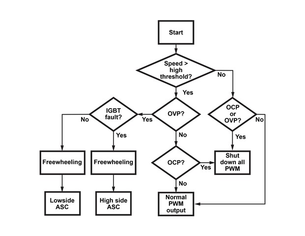
Another challenge for engineers is to be able to quickly put the motor into a safe state, such as freewheeling, in the event of faults. In the AM2634-Q1 device, a fault general-purpose input (for overcurrent, overvoltage or high-speed faults) routes to an innovative programmable real-time unit (PRU). Firmware executed in the PRU can correctly assess and respond to the type of fault and perform the desired PWM protection sequence, as shown in Figure 2, and then directly put the PWMs into a safe state as needed. These actions occur in little as 105 ns. Additionally, since the firmware is user-programmable, engineers can add additional custom logic if necessary to meet their application requirements.
 Figure 2 Flowchart Showing the Expected Protection Behavior for PWM Outputs Based on Fault Inputs
With the production of more EVs, design trends will shift toward SiC and 800-V technologies, along with the need to increase motor-control performance and meet functional safety requirements in traction inverters. As the world drives towards electrification, innovation in performance and efficiency will be critical to help auto manufacturers engineer the next generation of EVs.
Additional Resources
- See the application note, "AM263x for Traction Inverters."
- Explore the code that implements the motor-control loop.
- Read our detailed traction inverter benchmark analysis.