SSZT142 july 2021 TLV9041 , TLV9042
Note: Carolina Gomez collected the data for this article.
In my previous articles, I walked through optimizing an operational amplifier (op amp) circuit for power savings and talked about some of the applications that can take advantage of amplifiers with low-voltage-supply capabilities. In this installment of the "Designing with low-power op amps" series, I will show you how to save power with a more specialized device: the shutdown amplifier.
Shutdown Functionality
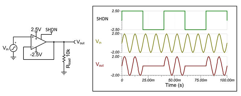
 Figure 1 TLV9002S Shutdown Toggle
Benefits of a Shutdown Pin
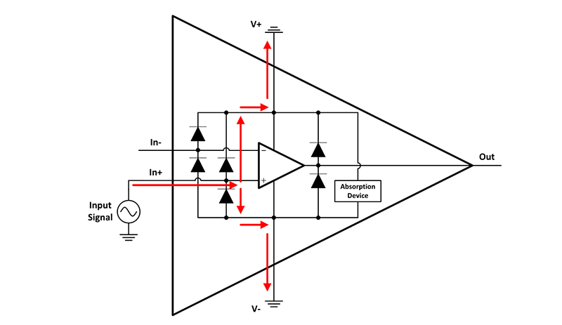
 Figure 2 Turning on an Op Amp’s ESD Diodes with an Input Signal
Another advantage to using the shutdown pin to turn off a device is that it can put the output into a known state. When an op amp goes into shutdown mode, the data sheet will often describe the output as becoming a high impedance node. When an op amp is merely turned off through the supply rails, the behavior of the output pin is undefined. Again, if in doubt, you can double-check this feature in the product data sheet. As highlighted in the technical article, “So what exactly is an op amp shutdown pin supposed to do?” other potential benefits of shutdown pins include digital logic compatibility, cost savings, space savings and a reduction in design complexity.
Shutdown Power Savings
 Figure 3
  Figure 4
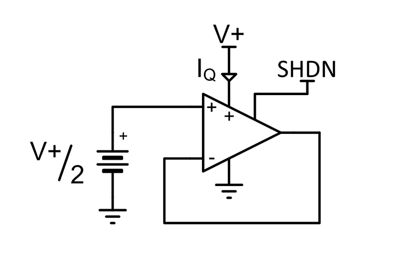
 Let’s now use some real-world measurements with Figure 3 and Figure 4 to estimate the potential shutdown power savings. For this example, consider the TLV9042S device in a unity gain buffer configuration. The input is tied to mid supply and the output is left without a load, as shown in Figure 5. My colleague, Carolina, powered on the unit at three common supply-voltage levels and measured the corresponding IQ, then placed the device into shutdown and measured the IQ again at each of the supply levels. Table 1 displays the measurements. Note that these results are slightly better than the data-sheet specification because the IQSD per channel is slightly lower for the dual-channel TLV9042 than for the single-channel TLV9041, whose more conservative value is quoted in the data sheet.
 Figure 5 TLV9042S IQ And IQSD Measurement Setup
| Device | Supply voltage (V+) | IQ per channel | IQSD per channel |
|---|---|---|---|
| TLV9042SIRUGR | 1.2 V | 9.545 µA | 50.965 nA |
| 3.3 V | 9.465 µA | 52.730 nA | |
| 5.0 V | 9.445 µA | 53.335 nA |
With the data from Table 1, you can now estimate the possible power savings for different low-power applications using the shutdown feature of the TLV9042S device. Depending on the low-power application, such as a photodiode amplifier or a battery-powered smoke detector, different duty cycles will help maximize power savings without sacrificing system functionality. With help from Figure 3 and Figure 4, along with the data in Table 1, it is possible to estimate the power consumed at different supply voltage levels when using the shutdown feature of the TLV9042S instead of leaving it always on. See the results in Table 2, where you can see that toggling the shutdown pin can lead to significant power savings.
| Supply voltage (V+) | Duty cycle | PAvg Consumed (µW) | PAvg Saved (µW) |
|---|---|---|---|
| 1.2 V | 80% | 9.175 | 2.279 |
| 1.2 V | 10% | 1.200 | 10.254 |
| 1.2 V | 1% | 0.175 | 11.279 |
| 1.2 V | 0.1% | 0.073 | 11.381 |
| 3.3 V | 1% | 0.485 | 30.750 |
| 5 V | 1% | 0.736 | 46.489 |
Conclusion
Additional resources- Catch up on other installments in the “Designing with low-power op amps” series.
- For a deeper understanding of the shutdown capability of a related product family, see the application report, “Designing for TLV90xxS Operational Amplifiers with Shutdown.”