SSZT150 june 2023 TPS543620 , TPS54620 , TPS566231 , TPS566238 , TPS62903
The features of a modern buck converter are simply tools to get a job done – and much like the utility belt of a certain Gotham City resident, the configuration and layout of these features were designed with space and flexibility in mind. Whether you wear a cape or not, having quick and easy access to these features means more than just solving design challenges – it means doing so without “bat”-ing an eye.
Historically, power-management solutions had independent pins for every function. Soft start, power good, switching frequency adjustment, loop compensation … every feature had a pin to go with it. This approach was (and continues to be) very beneficial. For example, the TPS54620 buck converter contains a separate power-good pin, which asserts a low signal in the event of a thermal shutdown. For products operating in harsher, more volatile conditions, having access to a pin that indicates whether your device is providing steady power is a necessity.
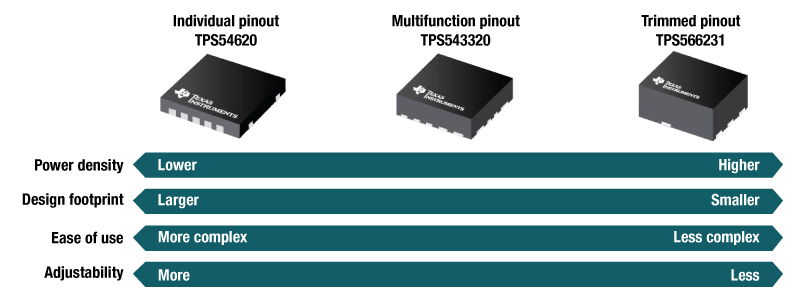
Even in the absence of extreme circumstances, your preferences toward power density, design footprint, ease of use, and adjustability can help you select an integrated circuit (IC) that’s more optimized for your needs. Figure 1 shows how the pinout you select addresses various design challenges.
 Figure 1 Pinout style vs. design
challenges
Figure 1 Pinout style vs. design
challengesOne distinct advantage of using individual pinouts is being able to finely tune each feature. When every feature has its own pin, your choice of resistor, capacitor or even short to ground allows you to set features such as the soft-start time anywhere within the device’s respective operating range. In contrast, multifunctional pinout devices and trimmed devices may have limited adjustability, or in some cases have these parameters fixed to a single value.
The Features We Deserve, but Not the Ones We Need Right Now
In some cases, you just need a silent guardian onboard – a converter that solves your design challenges with minimal oversight on your end. This is where trims become particularly useful. Device variants such as the TPS566231P and TPS566231 offer the option of choosing between a power-good pin and an adjustable soft-start pin. As you prioritize your design requirements, you might decide that power good isn’t much of a concern; you’re perhaps far more concerned about transients at startup. In that case, you could choose the TPS566231 for its adjustable soft-start (SS) capability and not worry about monitoring the signal provided by a power-good (PG/PGOOD) pin.
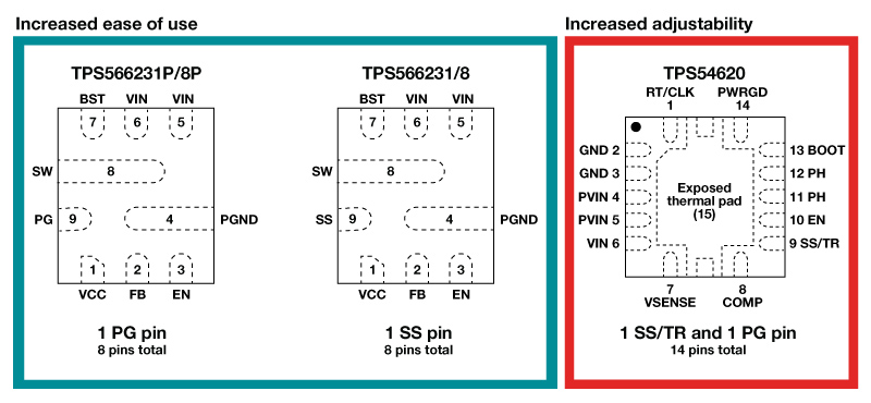
By limiting your pinout, you’re saving space beyond just the footprint of the IC. You are also actively reducing your external component count. Because these different trims have fixed parameters for many of the features you’d normally adjust with added external components, you’re saving a lot of time and space. Figure 2 illustrates how the TPS566231/1P/8/8P uses fewer pins without compromising device functionality. The reduced pinout of TPS566231/1P/8/8P allows for increased ease-of-use, whereas the more elaborate pinout of the TPS54620 gives you more adjustability to better optimize your power solution.
 Figure 2 TPS566231/1P/8/8P Pinout vs TPS54620 Pinout
It’s Not the Pinout but the Feature Set That Defines You
Like a watchful protector, it’s natural for designers to want to keep an eye on things. While limiting your pinout can be a lifesaver when space is tight, you can’t deny that the adjustability of parameters takes a back seat. Thankfully, there’s a solution to meet you halfway: the multifunctional pinout.
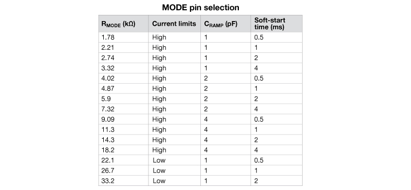
Devices such as the TPS543620 and TPS62903 offer a MODE pin, also known as a multifunctional pin, that enables the attachment of resistor configurations to select multiple parameters and compensation loops at once. In other words, it’s possible to simultaneously adjust things such as the ramp capacitor, soft-start time and current limit by connecting a few resistors to the IC. The MODE pin also saves you from having to consider the right resistor or capacitor values needed for adjusting a single parameter within the buck converter.
A data sheet of a multifunctional pinout device usually includes a table like the one in Figure 3, showcasing how different resistor values adjust different parameters within the IC.
 Figure 3 How RMODE Values Affect Internal Component Selection in a Given Device. RMODE Is the Resistor Placed at the Mode Pin.
No One’s Ever Seen a Headache and Great Design Together at the Same Time …
As you weigh your options when selecting a device that meets your power needs, you no longer need to associate power density or ease of use with a limited feature set. Packaging innovations over the years have enabled DC/DC buck converters to offer the features you need without compromising space on the board. And while pinouts on some devices may appear limited at first, you don’t have to be the world’s greatest detective to become aware of all of the tools at your disposal. With this knowledge, it’s only a matter of time before they build a signal to shine your name in the sky.
Additional Resources
- Read the technical article, “Advantages of scalability: from Peter Parker to pin-strapping.”
- Check out the white paper, “Understanding the Trade-Offs and Technologies to Increase Power Density.”