SSZT287 june 2020 BQ25790 , BQ25792
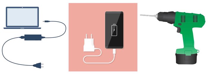
Today’s “always-on” consumer wants to charge their portable electronics wherever they are. For example, it’s common to see travelers charging their cellphones, laptops and headphones while waiting to board a flight or hop on a train. But when there are different charging methods for each device, these consumers must carry different adapters, and it can become quite a hassle to remember each adapter for each device (see Figure 1). For engineers to help minimize this hassle, their battery charging system designs must support charging from various input sources.
Why consider USB Type-C PD charging?
Designing a single-chip charger integrated circuit (IC) to charge multiple battery-powered devices with different configurations and different input-voltage ranges can be a complicated process, since classic adapters are not compatible with all battery-powered devices and traditional USB adapters are limited to 5-15 W, limiting the portable battery-powered devices they will support.
 Figure 1 Charging with different input
sources and adapters
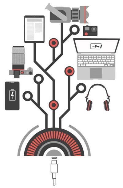
 Figure 2 Universal and fast charging
enabled by USB PD
Figure 2 Universal and fast charging
enabled by USB PDExpanding on the above example of a traveler charging one or more devices, the best-case situation given their potentially limited access to a power supply is that their devices will quickly charge to full battery capacity, and that the battery will last for an extended period of time once charged. Even if they only have a quick 15-minute layover to recharge a device, that should be enough to extend battery operation for hours.
Thus, to meet consumer expectations, design engineers are looking for solutions that can:
- Simplify their designs while enabling universal charging – the ability to charge multiple battery-powered devices with different configurations (1 cell in series [s] to 4s) and different input voltages.
- Extend battery run times and use the maximum battery capacity to enable the best consumer experience.
- Charge efficiently while reducing thermal dissipation to minimize power loss within the charger IC.
- Protect the input adapter, battery and system from a cascade failure.
TI’s new family of integrated buck-boost battery-charger ICs, including the BQ25790 and BQ25792, leverage USB PD input for improved flexibility in charging 1S – 4S batteries across an input-voltage range of 3.6 V to 24 V. With integrated components, these buck-boost chargers give you the freedom to choose whether a single-charger IC is a better design choice for compact, size-constrained battery-powered devices like cell phones, laptops, Bluetooth headsets or medical equipment vs. designing with multiple power stages that need either boosting up or bucking down to keep the application within a safe operating voltage range.
The BQ25790 and BQ25792 leverage an ultra-low power consumption charger IC to extend the battery’s run time during operation and to conserve as much battery power as possible when the application is not in use. In addition to ultra-low power consumption, the chargers come with a top-off timer that enables extra charging on top of a normal charge cycle, ensuring that the battery can charge to its maximum capacity (see Table 1).
| Parameter | Programmability | Resolution | Default |
|---|---|---|---|
| Charge voltage | 3 V-18.8 V | 10 mV | 4.2 V (1 cell in series [s]), 8.4 V (2s), 12.6 V (3s), 16.8 V (4s) |
| Charge current | 50 mA-5 A | 10 mA | 2 A (1s), 2 A (2s), 1 A (3s), 1 A (4s) |
| On-the-go (OTG) voltage | 2.8 V-22 V | 10 mV | 5 V |
| OTG current | 120 mA-3.32 A | 40 mA | 3 A |
| Pre-charge current | 40 mA-2 A | 40 mA | 120 mA |
| Termination current | 40 mA-1 A | 40 mA | 200 mA |
| Top-off timer | Disabled, 15 minutes, 30 minutes, 45 minutes | ||
For power designs that require a long run time, short and efficient charging, and a compact design, USB PD charging offers flexibility to charge a wide range of applications while keeping bill of materials low and shrinking total solution size. To learn more about designing with power density and low quiescent current in mind, check out the additional resources below.
Additional resources
- Read the technical article, Small chargers pack a powerful punch: combining buck-boost and USB Type C™ power delivery for maximum power delivery.
- Read the technical article, Transform the way you charge your devices with USB Type-C and PD.
- Watch the video, What could you achieve with universal and fast charging?