SSZT629 september 2018 MSP430FR2311 , MSP430FR2355
Ultra-low-power smart sensing and measurement demands more integration for the sensing analog front end (AFE), the analog-to-digital converter (ADC) and the microcontroller (MCU).
In this series, we are discussing some smart sensing applications and how to use TI’s MSP430™ MCU as a platform for implementing them. In this installment, I will be discussing two medical instruments: a blood glucose meter and a pulse oximeter. For a more in-depth look into the design implementation that is described for pulse oximeters in this blog, please refer to the app note “MSP430’s Analog Combo Enables True Single-Chip Pulse Oximeter Designs”.
A blood glucose meter is a small, portable machine that measures how much glucose (a type of sugar) is in the blood (also known as the blood glucose level). Normally, a small drop of blood, obtained by pricking the skin with a lancet, is placed on a disposable test strip that the glucose meter reads and uses to calculate the blood glucose level. The meter displays the level in units of milligrams per deciliter or millimoles per liter.
 Figure 1 A Blood Glucose Meter
Electrochemical test strips have electrodes where a digital-to-analog converter (DAC) applies a precise bias voltage. To measure the current which is proportional to the blood glucose, a transimpedance amplifier (TIA) converts the current to a voltage and followed by an ADC to convert the analog voltage to a digital signal. The dynamic range and minimum current requirement normally require a 12-bit-resolution ADC.
The results of a blood glucose test are displayed on a liquid crystal display (LCD), with an accompanying audio alert. For consumers with weak eyesight, an audible report is a popular feature. To implement this feature, a DAC has much better performance than pulse-width modulation (PWM) for the audio playback.
The electrochemical test strips are temperature-dependent. So getting the correct glucose result requires measuring the ambient temperature for the temperature compensation algorithm.
Since a blood glucose meter is powered by batteries, there is a requirement to monitor the battery voltage and display it on the LCD or provide warning messages to users if the battery power is used up. Normally, a comparator or ADC handles this requirement. But a comparator consumes less power than an ADC.
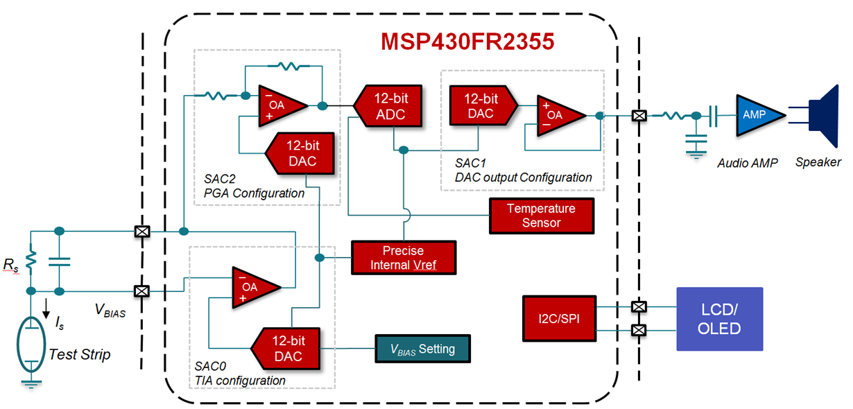
The MSP430FR2355 mixed-signal MCU features configurable signal-chain elements that can help implement a blood glucose monitor except the LCD. There are four Smart Analog Combo modules in the MSP430FR2355. Each module can be configured to an operational amplifier (OA), a programmable gain amplifier (PGA) or a 12-bit DAC.
For a blood glucose monitor application, you can configure:
-
One module to a TIA for electrochemical test strip current measurement. The typical 50pA input bias current of the operational amplifier can help the small current measurement.
-
One module to a PGA and work with the 12-bit ADC to get high-resolution analog-to-digital conversion.
-
One module to audio output and work with external low-pass filter and audio amplifier to achieve high-performance audio playback.
Figure 2 illustrates all three configurations.
 Figure 2 SAC Configuration Example for
a Blood Glucose Meter
Figure 2 SAC Configuration Example for
a Blood Glucose MeterThe built-in internal voltage reference has three voltage options: 1.5V, 2.0V or 2.5V. You can use this reference for the DAC reference voltage. Setting the DAC input generates a precise bias voltage for electrochemical test strips.
You can use the built-in temperature sensor for temperature compensation and the built-in enhanced comparator as a battery voltage monitor and wake-up detection.
There are rich interconnections in the signal-chain elements to enable many configuration options without external connections or less external components.
With 32KB of ferroelectric random-access memory, the MSP430FR2355 MCU offers an ultra-low-power and fast write speed for glucose history data logging.
Pulse Oximeter
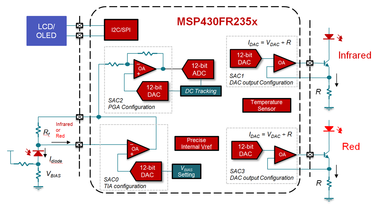
A pulse oximetry application requires an MCU-integrated operational amplifier, DAC and ADC. But a few different from a blood glucose meter, a pulse oximeter detects light absorption which is emitted from two LEDs. The MSP430FR2355 MCU is also a good fit for this application. For a pulse oximeter application, you can configure:
-
One module to a TIA for photodiode current measurement.
-
One module to a PGA and work with the 12-bit ADC to get high-resolution analog-to-digital conversion, with the DAC used as DC tracking filter.
-
One module to DAC for Infrared LED driving with dynamic strength configuration
-
One module to DAC for Red LED driving with dynamic strength configuration
Figure 3 illustrates all four configurations.
 Figure 3 SAC Configuration Example for
a Pulse Oximeter
Figure 3 SAC Configuration Example for
a Pulse OximeterYou can use the built-in temperature sensor for temperature compensation of the LED strength or photodiode temperature drift. You can also use the built-in internal voltage reference, enhanced comparator and ferroelectric random-access memory to implement the system functionalities as mentioned in above sections.
For a detailed pulse oximeter application operation theory and design implementation, see the application report, “MSP430’s Analog Combo Enables True Single-Chip Pulse Oximeter Designs”.
And for more information about how to use Smart Analog Combo modules in your design, see the application report, “How to Use the Smart Analog Combo in MSP430 MCUs.”
Additional Resources
- Learn more about the design of a pulse oximeter in the application report, “MSP430’s Analog Combo Enables True Single-Chip Pulse Oximeter Designs”.
- Download the “MSP430FR2355 LaunchPad™ Development Kit User’s Guide.”
-
Check out the “MSP430FR2311 IR Reflection-Sensing Subsystem Design Guide.”
-
Learn “How to Use the Integrated Operational Amplifiers on the MSP430FR2311.”