SSZT878 November 2017 LM5017 , LM5160 , LM5160-Q1 , LM5160A , LM5161 , LM5161-Q1
More and more drone applications require high-cell-count battery packs to support longer flying distances and flight times. For example, consider a 14-series lithium-ion (Li-ion) battery pack architecture where the working voltage is 50V to 60V. When designing a DC/DC power supply for such a system, one of the challenges is how to select the maximum input voltage rating. Some engineers see an outsized voltage excursion at the node designated VM in Figure 1, but may not be aware of its origin or how to deal with it.
 Figure 1 Drone System Block
Diagram
Figure 1 Drone System Block
DiagramFirst, let me explain the modes of operation of a motor driver. As shown schematically in Figure 2, the battery stack powers a brushed-DC (BDC) motor, M1, through the forward current path designated as loop 1, and electric power converts to the motor’s rotational kinetic energy during this period. Conversely, when the motor decelerates or changes its direction of rotation, it acts as a generator; the resulting back electromotive force (EMF) returns energy to the input through the driver via current loop 2.
Although this action may seem advantageous in terms of improving overall system efficiency, the regenerative behavior can result in a large reverse current and consequent voltage overshoot at the supply input.
 Figure 2 Forward Current Paths of a BDC
Motor H-bridge Driver
Figure 2 Forward Current Paths of a BDC
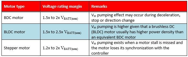
Motor H-bridge DriverTable 1 outlines typical voltage-rating margins for different motor types. The overshoot voltage range (relative to the nominal battery operating voltage) also depends on the drone’s flight dynamics and control algorithm for the thrust and direction change of each propeller.
|
In order to manage this voltage overshoot and ensure that the system runs safely, you can use an electrolytic bulk capacitor for C1 to absorb the energy or, alternatively, add a transient voltage suppressor (TVS) diode to clamp the voltage to a safe range.
Take the Rubycon 2200µF/63V electrolytic capacitor, for example. Its diameter and height are 18mm and 33mm, respectively – quite large to go in a drone implementation where footprint and profile are important constraints. The 1,000-unit price of this capacitor is more than $1.00 from a distributor such as Digi-Key. More important is that this electrolytic capacitor, with its finite rated lifetime, represents an acknowledged limitation in terms of system reliability and robustness. A TVS clamp also creates space, cost and reliability concerns for the whole system.
Another option is to use a DC/DC converter solution with a wide input voltage range and high-line transient immunity to accommodate the full voltage excursion during the motor’s regenerative action.
Selecting a converter with a wide VIN range, such as the LM5161 100V, 1A synchronous buck converter from TI (see Figure 3) enables you to eliminate the bulk energy storage or TVS clamp, saving time, cost and board space. Moreover, the LM5161 converter offers a large degree of flexibility in terms of platform design. Not only does it support a non-isolated output, but the converter can also deliver one or more isolated outputs – using a Fly-Buck™ circuit implementation – if it’s necessary to break a ground loop or decouple different voltage domains in the drone system. If a VCC bias rail between 9V and 13V is available, the LM5161’s input quiescent current reduces to 325µA at a 50V input to uphold battery life during standby operating conditions.
 Figure 3 LM5161 Step-down Converter
Schematic
Figure 3 LM5161 Step-down Converter
SchematicSummary
Additional Resources
- Order the evaluation module for the LM5161 100V synchronous buck converter.
- Download the LM5161 quickstart calculator.
- Peruse these reference designs for drones:
- Non-Military Drone, Robot or RC 2S1P Battery Management Solution Reference Design.
- Sensorless High-Speed FOC Reference Design for Drone ESC.
- 4.4 V to 30 V, 15 A, High Performance Brushless DC Drone Propeller Controller Reference Design.
- High Density Efficient Solution for Main Aux As Well As Back Up Aux Power in Drones.”
- Review the white paper, “Valuing wide VIN, low EMI synchronous buck circuits for cost-driven, demanding applications.”