SSZT887 November 2017 TPS53622 , TPS53647 , TPS53659 , TPS53667 , TPS53679 , TPS53681
In a previous Power House blog post, I introduced TI’s D-CAP+ multiphase regulator control topology and covered the basics of its architecture, steady-state operation and transient performance versus a competitor’s part. I also said something when listing some of the features of the D-CAP+ control topology that at first glance just seems like a marketing claim: that the overall regulator stability is insensitive to load current, input voltage and number of phases. The math behind the modulator checks out, so I went to the lab to take some Bode plots and evaluate the D-CAP+ control topology in the real world.
While holding all parameters constant and only changing VIN, IOUT or the number of phases, I used a network to generate a number of Bode plots across a wide range of conditions. For my testing, I used the TPS53679 multiphase controller under these conditions:
- VIN = 8V, 12V, 16V.
- VOUT = 1V, fSW = 400kHz.
- Number of phases = two, four, six.
- IOUT = 50A, 100A, 150A.
In Figure 1, I took plots at VIN = 8V, 12V and 16V. DC gain and dominate pole frequency were identical for all three curves and there was little variation in crossover frequency and phase margin. All three curves showed a stable system; changing the input voltage did not affect the performance of the D-CAP+ modulator.
 Figure 1 Loop Response vs. Converter
Input Voltage
Figure 1 Loop Response vs. Converter
Input VoltageIn Figure 2, I changed the number of active phases from two to four to six while holding everything else in the design constant. Once again, there was very little variation in any of the Bode plots and no instabilities. D-CAP+ stability is not dependent on phase number. The modulator was two for three, with one test to go.
 Figure 2 Loop Response vs. Converter
Phase Number
Figure 2 Loop Response vs. Converter
Phase NumberFor the last test, I took Bode plots at 50A, 100A and 150A, and for the third time, the D-CAP+ control topology proved to be insensitive to changes in operating conditions. The plots in Figure 3 all came out stable and identical to one another.
 Figure 3 Loop Response vs. Converter
Load Current
Figure 3 Loop Response vs. Converter
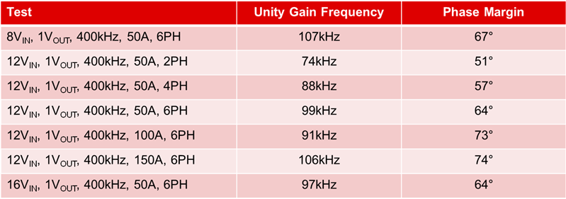
Load CurrentTable 1 summarizes the unity gain and crossover frequencies of all of the Bode plots I took during my time in the lab. Under all conditions, there’s more than adequate phase margin (>50 degrees) at the unity gain frequency, making stability a non-issue. With an easily achievable loop bandwidth around a quarter of the switching frequency for most conditions, the reason for the D-CAP+ control topology’s excellent transient response becomes apparent. A higher bandwidth gives the controller a much quicker response time to load transients and less over- and undershoot on VOUT as a result. With stability practically guaranteed over a wide range of operating conditions, designing with the D-CAP+ modulator becomes even easier.
|
I’d like to note that I did not once touch any compensation parameters during testing. The D-CAP+ control topology allows you to dial in the compensation for your chosen output filter and not worry about stability over your expected operating corners. Lowering the loop bandwidth to ensure stability and eke out that last bit of phase margin while sacrificing transient response is a thing of the past with this modulator. The performance is really there.
Additional Resources
- I used the TPS53679 because I had a board handy for testing, but you can get the same performance out of any of TI’s D-CAP+ multiphase regulators, including the TPS53647, TPS53667, TPS53659, TPS53622 and the newly released TPS53681.
- For more information on how a D-CAP+ regulator performs in high-current networking applications, download the High-Power 6+1 Voltage Regulator Reference Design for Networking ASICs.