SSZT944 september 2017 LM3880 , LM3881 , UCD9090A
As electronics increase in complexity, designers of even simple systems are running into issues associated with multiple power rails. One challenge with having multiple power rails is often the sequencing of the enable signals, because the startup order and timing of these rails can be strict.
The LM3880 and LM3881 analog power-supply sequencers offer a simple method to control the power-up and power-down sequencing of multiple independent voltage rails. By staggering the startup sequence, it is possible to avoid latch conditions or large in-rush currents that can affect system reliability. The LM3880 has fixed time-delay options for sequencing, while the LM3881 offers variable time delay based on an external capacitor.
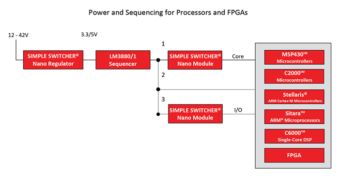
One of the most common places you'll see this need is in a system that includes a field-programmable gate array (FPGA) and/or processors and controllers such as a digital signal processor (DSP) or a microcontroller unit (MCU). Figure 1 shows an example of how you might use the LM3880 or LM3881 in such a system.
 Figure 1 Using the LM3880 or LM3881 for
sequencing processors and FPGAs
Figure 1 Using the LM3880 or LM3881 for
sequencing processors and FPGAsAs you can see, a single LM388x controls up to three voltage rails on its own. You can, however, cascade multiple LM388x devices together in order to sequence additional rails. Each device you add allows you to sequence three additional rails, although if you require sequencing for more than nine rails, it is best to consider a PMBus high-rail-count digital sequencer like the UCD9090A, which can handle 10 rails.
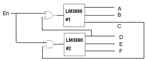
Cascading the LM388x is a very easy task, requiring only two logic gates. The first step is to add an AND gate at the enable signal of the second LM388x with the third rail of the first LM388x as shown in Figure 2. This AND gate ensures the proper power-up sequence by preventing the second LM388x from starting its turn-on until the first LM388x has brought all three of its rails high. The second step is to add an OR gate at the enable of the first LM388x with the first rail of the second LM388x, also shown in Figure 2. This OR gate ensures the proper power-down sequence by preventing the second LM388x from starting its turn-on until the first LM388x has brought all three of its rails low.
 Figure 2 Cascading Two LM3880
Devices
Figure 2 Cascading Two LM3880
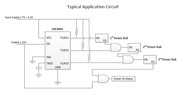
DevicesLogic gates can also be useful if you require supervision and monitoring of the rails. You can add three AND gates to the system in-between each rail and between the third rail and a power-on status flag to monitor when all devices are fully powered on. With this simple modification, the power-on status will go active immediately after all three rails power up and will go inactive when the enable turns off, showing that the device is beginning its power-down sequence. Figure 3 shows this application circuit.
 Figure 3 Using AND gates to add
supervision
Figure 3 Using AND gates to add
supervisionWith all of these capabilities, how does the LM388x stack up against other potential solutions? Against more feature-rich (and complex) digital sequencers that provide more functionality (with higher system cost), the LM388x maintains its edge with ease of use, requiring no programming whatsoever, and a very low-cost system approach at nearly tenth the cost of the cheapest digital sequencers. Against a basic discrete solution, the LM388x once again wins when it comes to ease of use, as you can add it to a system as a single device in most cases, allowing not only power-up sequencing but power-down sequencing as well. Compared to other simple analog sequencers, the LM3880 and LM3881 are much simpler; except for a small timing capacitor in the LM3881's case, they require no external components.