SSZTA02 january 2017 ADS131E08S
A circuit breaker is one of the most essential components of an electrical power system, used in electrical transmission and distribution networks to protect equipment or circuits during fault conditions such as a short circuit or overload by interrupting the circuit. Industrial breakers are generally three- and four-pole designs, with current-interrupting capability ranging from few hundreds of amps up to 6.3kA. For one- or two-pole residential breakers, miniature circuit breakers (MCBs) offering only overcurrent protection are very common. Arc fault current interrupters (AFCIs) and ground fault current interrupters (GFCIs) are special-function breakers that interrupt during arc faults and ground faults, respectively.

Interrupting a high current and/or voltage during fault conditions results in an arc. The length of the arc depends on the voltage levels and intensity of the interrupting current. Different mechanisms and mediums like vacuum, air, insulating gas, sulfur hexafluoride or oil contain, cool and extinguish the arc to control the intensity. Residential applications use MCBs <100A, with thermal or thermal magnetic-type breaking mechanisms. Low- and medium-voltage systems use molded-case circuit breakers (MCCBs), which are available for up to 2.5kA-4kA of current, and offer additional features like an adjustable trip mechanism. Air circuit breakers (ACBs) are available in a range from 630A up to 6.4kA. During a short circuit, ACBs open the circuit within 40ms to 60ms, allowing more than two cycles of fault current through before opening. Loads protected by an ACB (for example, transformers and bus bars) must be rated to withstand fault current for a short duration.
A circuit breaker consists of current and voltage sensing, analog signal conditioning, a microcontroller (MCU), a power-management block, and an actuation driver/tripping unit. It may also include an analog-to-digital converter (ADC), either external or as a peripheral internal to the MCU. One important subsystem in a modern MCCB or ACB is the electronic trip unit (ETU), which performs tasks like true root-mean-square (RMS) current sensing, adjustable trip time, zone-selective interlocking, and self-powering and communications. Current transformers (CTs) or Rogowski coils sense and measure a wide range of input current.
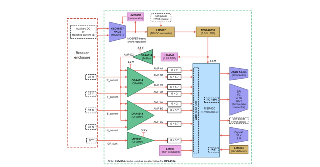
MCCBs are a high-volume market, where the cost of the system needs to be as low as possible. This is possible by sensing current using a 12-bit successive-approximation-register (SAR) ADC that is built into TI’s MSP430™ MCU, as demonstrated in the Signal Processing Subsystem and Current Input-Based Self Power for Breaker Applications (ACB/MCCB) reference design. Figure 1 shows the block diagram of the signal-processing front end for the ETU. This system provides a fast startup time of <30ms and includes one-cycle true RMS calculation, with an accuracy of <±3%. Amplifiers with two gains measure a wide range of current, with higher accuracy for both protection and metering. The reference design also demonstrates self-powering of the system by using power from CTs.
 Figure 1 Signal Processing Subsystem
and Current Input-Based Self Power for Breaker Applications Reference Design
Block Diagram
Figure 1 Signal Processing Subsystem
and Current Input-Based Self Power for Breaker Applications Reference Design
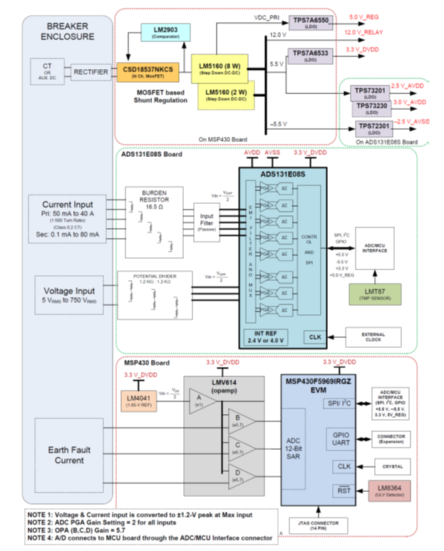
Block DiagramUnlike MCCBs, ACBs need high performance and accurate analog signal processing at the front end for wider input-current ranges; the resolution of the ADC built into the MCU may not be sufficient for this application. The High Resolution, Fast Startup Analog Front End for Air Circuit Breakers reference design demonstrates higher measurement accuracy at the lowest possible cost by using the ADS131E08S external ADC, a 24-bit delta-sigma data converter with eight-channel simultaneous sampling capability, as shown in Figure 2. ACBs are specified to trip within 35ms to 40ms while powered under a fault condition. This trip time includes system power up, AC current measurement and breaking the fault current. The ADS131E08S starts up in <3ms, contributing to a reduced overall startup time. The ADC’s programmable gain amplifier (PGA) reduces the need for external components, improving temperature performance and reliability. A 24-bit data converter provides accurate input AC voltages and currents for a dynamic range of 1000V/500A.
 Figure 2 Analog Front End for ACB Block
Diagram
Figure 2 Analog Front End for ACB Block
DiagramTI provides analog, digital, power and MCU solution required for designing of ETU in circuit breakers. TI products and system solutions enable faster development of subsystems within the circuit breaker with optimized cost and excellent performance.
Additional Resources
- Learn more about simplifying circuit breakers using delta-sigma ADCs.
- Download the data sheet for the ADS131E08S data converter.