SSZTAH2 january 2017 TPS2514A , TPS25740 , TPS25740A , TPS65982
USB chargers are becoming more and more prevalent, and seem on their way to becoming universal. They’ve gone from just being on your computer to being in wall outlets, wall warts, car panels, airplane seats, and more.
Traditional USB Type-A chargers have just one voltage, which lends itself to a simple high-level design. Figure 1 shows a simplified schematic. The resistor divider formed by RFBL and RFBU enables closed-loop regulation of the output voltage applied to VBUS. In this topology, the flyback controller must limit the output current for safety.
 Figure 1 Traditional USB Charger
Schematic for Type-A Receptacles
Figure 1 Traditional USB Charger
Schematic for Type-A ReceptaclesUSB Power Delivery (PD) on the USB Type-C™ connector enables higher power charging, which will broaden the USB charging ecosystem even more. However, USB PD and USB Type-C have new requirements, for which the schematic in Figure 1 is not sufficient.
Figure 2 shows a simplified schematic for a USB PD charger. Right away, you can see that there are two MOSFETs in the power path and a bulk capacitance that were not there in Figure 1. Notice also that this schematic can deliver multiple voltages. The PD controller negotiates voltages over the configuration channel (CC) and then pulls the CTL1 and/or CTL2 pins low to adjust the resistor divider to get a voltage higher than 5V. The CTL pins are either pulled to ground or set to high impedance by the PD controller to select the desired output voltage.
 Figure 2 USB Type-C PD Charger
Schematic for Type-C Receptacles
Figure 2 USB Type-C PD Charger
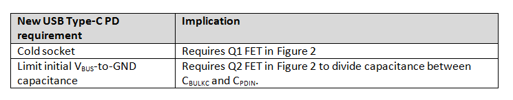
Schematic for Type-C ReceptaclesUSB Type-C has some requirements that are different from USB Type-A. Table 1 summarizes the two new requirements discussed here and their implications.
|
The first new requirement is that USB PD-capable chargers must be cold socket; in other words, VBUS is at 0V when the plug is empty. Also, when faults occur, the source is required to drive VBUS to 0V for close to 1s as it performs a USB PD Hard Reset. Driving VBUS to 0V requires a way to disconnect the flyback output from the VBUS on the connector while maintaining the PD controller supply. The schematic in Figure 2 uses the Q1 FET to allow VBUS to go to 0V, while the PD controller keeps its supply input (VPWR) high so that it can monitor for a sink attachment on CC1 and CC2.
In the USB specification, “0V” really means less than 0.8V (referred to as vSafe0V in the specification). This ensures that any attached USB device or sink detects that VBUS has gone away and resets. Although the USB specification requires USB self-powered peripherals to detect anything other than transients below 4.0V as a detach (USB 3.1 Section 7.5.1.2.4), it does not specify the detach voltage for other peripherals. It is common for USB devices to operate at even lower voltages. Therefore, the 0.8V definition ensures that all devices detect the detachment.
The second new requirement is that the Type-C receptacle cannot expose more than 10µF to VBUS when the receptacle is empty. The schematic in Figure 2 uses the Q2 FET to block in-rush current into CBULKC. Q2 divides the capacitance so that CPDIN applies directly to VBUS on the connector, and CBULKC is isolated from the connector. Since USB PD may provide up to 100W, the CBULKC capacitance may be very large. The USB 3.1 specification gives several reasons to limit capacitive in-rush, including limiting contact arcing to prolong the life of the connector (see USB 3.1 Section 11.4.4.1), which led to requiring USB Type-B ports limit capacitance exposed on the VBUS pin of their receptacle to 10µF.
The USB Type-C specification defines cables that adapt a legacy A plug to a C plug (see Figure 3), meaning that the hot VBUS from a Type-A receptacle can be connected to VBUS of the USB Type-C receptacle. Therefore, to protect legacy Type-A ports, all Type-C receptacles must limit their capacitance while not sourcing VBUS to the same 10µF limit for Type-B ports.
 Figure 3 USB Type-A Plug to USB Type-C
Plug
Figure 3 USB Type-A Plug to USB Type-C
PlugFinally, a USB PD charger has the option of implementing a captive cable. A captive-cable product has a Type-C plug instead of a Type-C receptacle. The USB Type-C specification does not define a Type-C receptacle (female) to a Type-A plug (male). Therefore, the capacitance on the VBUS pin does not need to be limited since it is not meant to be mechanically connected to a Type-A port. This leads to the optimization shown in Figure 4, where the Q2 FET has been removed but the Q1 FET remains so that VBUS can be driven to 0V. Another benefit of the captive-cable application is that it only needs one CC pin, since the Type-C plug only has one CC pin.
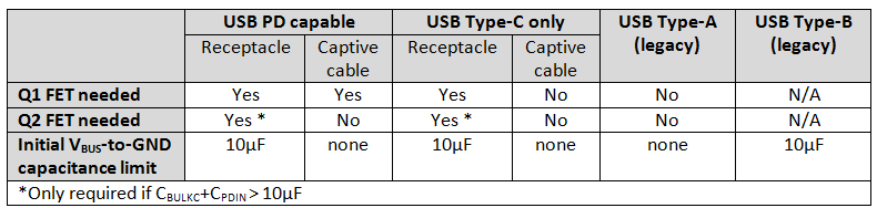
Table 2 summarizes the applicability of these two new requirements for different applications.
|
For systems where Q1 and/or Q2 are required (i.e., all USB PD applications), system designers can minimize the system impact by selecting FETs with smallest RDS(on). Since N-channel MOSFETs generally offer lower RDS(on) than P-channel MOSFETs, it is best to select a PD controller that can directly control N-channel MOSFETs such as TI’s recently released TPS25740 and TPS25740A USB PD controllers.
.") Figure 4 USB Type-C PD Charger
Schematic for Type-C Plug (Captive Cable).
Figure 4 USB Type-C PD Charger
Schematic for Type-C Plug (Captive Cable).As with all new technologies, there are many details to be considered when developing a USB Type-C charger. It is not just a copy-paste from an existing USB Type-A product. Download a USB Type-C charger reference design today and upgrade your USB design for higher power charging.
Additional Resources:
- Learn about:
- Read the application note: TPS65982 Designs for Supporting Voltages in USB-PD "Power Rules