SSZTAP3 november 2016 TPS659037 , TPS65916
Nov 1, 2016
When designing a power solution for an application processor, your first considerations are often the number of rails needed, the output voltage and the maximum load current. There are tools like the Quick Search that can help you select the right power-management IC (PMIC) for the processor or application, whether it’s an industrial application like Factory Automation or Human Machine Interface (HMI), or an automotive application like infotainment or advanced drivers assistance systems (ADAS).
But you also need to ask yourself:
- How will you handle power-up and power-down sequencing?
- How will you ensure the completion of the power-down sequence when power is removed?
Let’s take a look at these questions in more detail.
Power-up and Power-down Sequencing
An easier way is to use the PMIC’s one-time programmable (OTP) memory, which contains default output voltages and power-up and power-down sequencing for the device. So when the PMIC is enabled or disabled, a pre-programmed sequence will execute without any interaction from a microcontroller. The PMIC can also start the power sequence within a few milliseconds, which leads to faster boot times than when booting up a microcontroller before running power sequencing.
Using the PMIC in different configurations doesn’t require any different firmware, or actually any firmware at all. For example, the TPS659037 has two different configurations, based on the orderable part number, to power the AM572x Sitara™ depending on processor frequency and the number of cores used. The PMIC will enable or disable core rails depending on the configuration. So you can use the same PMIC in two different configurations, with no hardware changes or additional firmware development. Configurations for other processors or applications are possible by programming a different sequence in the OTP memory.
Power-down Sequence When Power Is Removed Unexpectedly
- A supervisor, which creates a logic signal to indicate that power is good, for systems where VIN directly powers the PMIC.
- A power-good signal for systems using a pre-regulator to generate the PMIC supply.
Figure 1 shows the implementation of the first option, while Figure 2 shows the implementation of the second option.
 Figure 1 Supporting Uncontrolled Power
Down When vIN Powers the PMIC
Figure 1 Supporting Uncontrolled Power
Down When vIN Powers the PMIC Figure 2 Supporting Uncontrolled Power
Down When a Pre-regulator Powers the PMIC
Figure 2 Supporting Uncontrolled Power
Down When a Pre-regulator Powers the PMICIn the case of the pre-regulator, the pre-regulator output capacitance can also act as the energy storage to hold VCC up. You should base your chosen total supply capacitance on the worst-case leakage current during power down so that the voltage is held up until the power-down sequence completes.
Use Equation 1 to calculate the required capacitance:
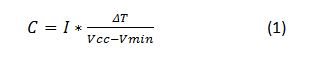
Where I is the leakage current, Vcc is the supply voltage to the PMIC, Vmin is the minimum input voltage the PMIC needs to operate, and ΔT is the time it takes the power-down sequence to complete. For TI’s TPS659037 and TPS65916, Vmin is 2.75V, and the pre-programmed power-down sequence is typically 1ms.
See our PMIC page to learn about more ways to enable your system power with TI’s broad portfolio of scalable PMICs.
Additional Resources
- Download these user’s guides: