SSZTAQ2 october 2016
In my last blog post, we looked at electromagnetic compatibility (EMC) and electromagnetic interference (EMI) requirements for industrial drives.
Why would we develop hardware with isolation? We can isolate sensitive measurement from noisy supply domains for improved accuracy, reduction of common mode noise although isolation may not be required due to safety. We call this functional isolation.
The most obvious reason for isolation is the safety aspect to protect against electrical shock. A system must ensure protection from hazardous voltages. If these voltages are present in a system isolation is mandatory.
There are two levels of isolation:
- Systems with basic isolation provide a single level of isolation with basic protection against electric shock.
- Systems with double isolation are comprised of two independent layers of basic insulation. Another independent insulation is added in addition to the basic insulation to ensure protection against electric shock in the event of a failure of the basic insulation.
Systems with reinforced isolation provide a single insulation system that provides a degree of protection against electric shock equivalent to double insulation under the conditions specified by the corresponding standards.
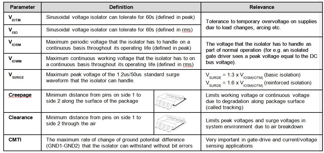
For variable speed drives the relevant standard is the IEC 61800-5-1. The corresponding semiconductor level standards are for example the IEC 60747-5-5 for optical isolators and for capacitive/magnetic isolators the VDE0884-10/11 and the draft version of IEC 60747-17. What are key parameters specified? The IEC 61800-5-1 specifies the level of insulation required between high voltage and conductive parts/equipment surface, in terms of:
- Transient overvoltage (corresponds to VIOTM)
- Surge voltage (corresponds to VSURGE)
- Creepage
- Clearance
This is depending on depending on:
- Basic or reinforced isolation is required
- System voltage
- Working voltage (corresponds to VIORM)
- Overvoltage category
- Pollution degree
- Package material
Let’s have a look at a hardware design example of an industrial drive’s 3-phase AC inverter. The AC inverter is typically fed from the 3-phase AC grid. The amplitude of the 3-phase AC typically specifies the DC-link voltage. To isolate the microcontroller from the power stage, isolated IGBT gate drivers as well as isolated phase current and voltage sensors are used.
How can we retrieve the isolation voltage requirements from the AC or DC input voltage?
The IEC61800-5-1 specifies the corresponding electrical parameters like temporary overvoltage, impulse surge voltage, minimum clearance and creepage for basic of reinforced isolation based on the system voltage along with other parameters like category, pollution degree and altitude. The relevant system voltage per IEC61800-3 is for example 300V, 600V and 1000V. The system voltage specified by the vendors must not be lower than the relevant IEC61800-3 voltage.
For example for a system specified for 830Vrms, the IEC61800-5-1 requirements for 1000Vrms will be valid. The maximum sinusoidal peak voltage to tolerate for 60s is 6.2kVpk, the maximum surge voltage is 12kVpk and the maximum peak working voltage is 830Vrms.For systems to pass IEC61800-5-1 the temporary peak and surge voltages for reinforced or basic isolation depend on the system voltage. Note that for semiconductor isolators the relevant components standard requires isolators with reinforced isolation pass at least 10kV surge.
How do we select the right semiconductors and what are the hardware design considerations to meet the isolation requirements? The Isolated IGBT Gate Driver Evaluation Platform for 3-Phase Inverter System Reference Design is a good example for a reinforced isolated IGBT gate driver evaluation platform for 3-phase inverter systems. This design supports up to 1500Vrms working voltage. The design has been tested with motors up to 22kW and exceeds the IEC61800-3 EMC immunity for power interfaces with 8kV ESD contact discharge and 4kV EFT by twice the required voltage level. Isolation requirement, terminology and a TI hardware design example are explained in the training video series Section 5: Isolation requirements in industrial drives.
If you’re ready to learn more, watch the training series Design considerations for EMI, EMC immunity and isolation requirements or download the corresponding Motor Drive & Control system reference designs.
If you would like to see more on specific topics related to design consideration for EMI, EMC immunity and isolation requirements in industrial drives, please post a comment below.
Additional Resources:
- View all TI motor drive reference designs.
- Watch the new video training series: Design considerations for EMI, EMC immunity and isolation requirements in industrial drives.
- Download the white paper, “Understanding electromagnetic compliance tests in digital isolators.”
- Read the Analog Applications Journal article, “Design considerations for system-level ESD circuit protection.”
- Check out and download these white papers:
- High-voltage reinforced isolation: Definitions and test methodologies, Anant S Kamath, Kannan Soundarapandian, Texas Instruments
- Understanding electromagnetic compliance tests in digital isolators, Sarangan Valavan, Texas Instruments
- Design considerations for system-level ESD circuit protection, Roger Liang, Analog Applications Journal, Texas Instruments